memory array and are not affected by an ERASE or MASS ERASE operation. The bits in these
registers can be changed from 1 to 0 with a commit operation. The register contents are unaffected
by any reset condition except power-on reset, which returns the register contents to 0xFFFF.FFFE
for the BOOT Configuration (BOOTCFG) register and 0xFFFF.FFFF for all others.
By committing the register values using the COMT bit in the Flash Memory Control (FMC) register,
the register contents become non-volatile and are therefore retained following power cycling. Once
the register contents are committed, the only way to restore the factory default values is to perform
the sequence described in “Recovering a "Locked" Microcontroller” on page 213.
All of the FMPREn, FMPPEn and USER_REGn registers, in addition to the BOOTCFG register can
be committed in non-volatile memory. The FMPREn, FMPPEn, and USER_REGn registers can be
tested before being committed; the BOOTCFG register cannot. To program the BOOTCFG register,
the value must be written into the Flash Memory Data (FMD) register before it is committed. The
BOOTCFG configuration cannot be tried and verified before committing to non-volatile memory.
Important: All Flash memory resident registers can only have bits changed from 1 to 0 by user
programming. The FMPREn, FMPPEn and BOOTCFG registers can be committed
multiple times, but the USER_REGn registers can only be committed once, after the
entire register has been set to 1s. After being committed, the USER_REGn registers
can only be returned to their factory default values of all 1s by performing the sequence
described in “Recovering a "Locked" Microcontroller” on page 213. The mass erase of
the main Flash memory array caused by the sequence is performed prior to restoring
these registers.
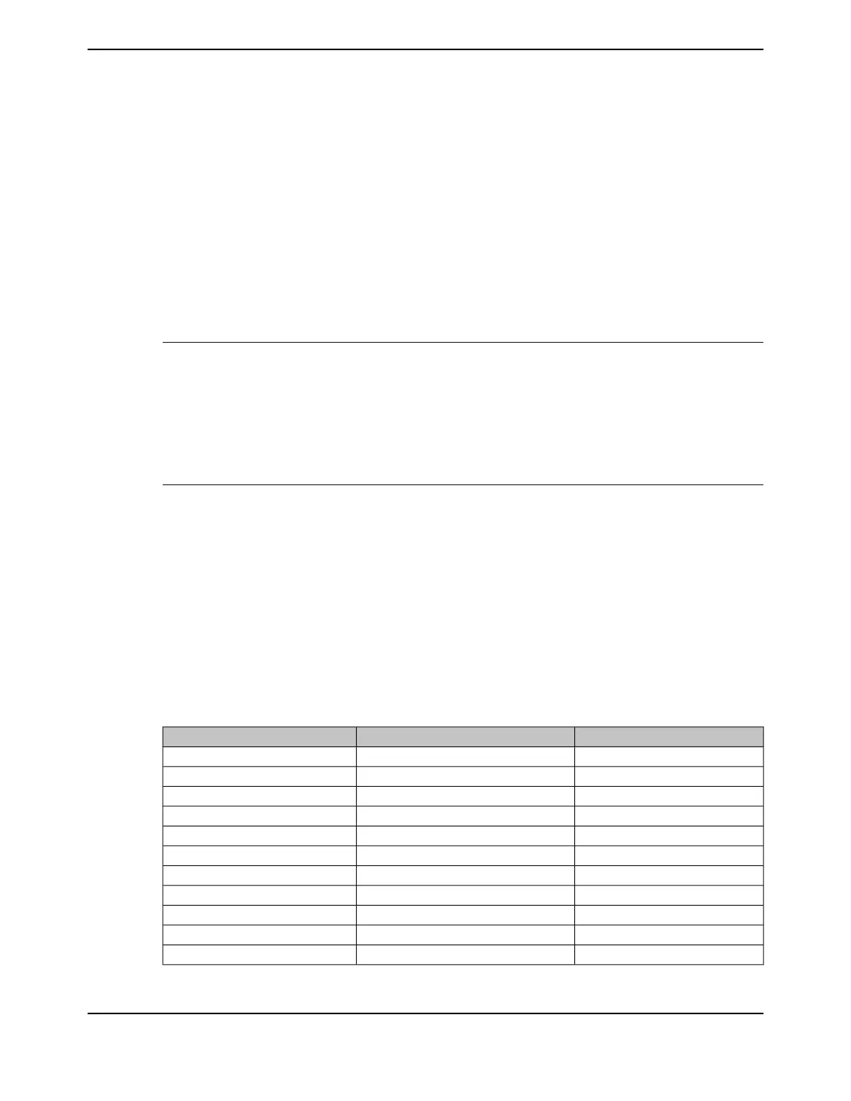
Table 8-3 on page 614 provides the FMA address required for commitment of each of the registers
and the source of the data to be written when the FMC register is written with a key value of 0xA442
or the PEKEY value of the FLPEKEY register. The key value used is determined by the KEY bit in
the BOOTCFG register at reset. If the KEY value is 0x0, the PEKEY value in the FLPEKEY register
is used for commits in the FMC/FMC2 register. If the KEY value is 0x1, the value 0xA442 is used
as the WRKEY in the FMC/FMC2 register. If the After writing the COMT bit, the user may poll the FMC
register to wait for the commit operation to complete.
Note: To ensure non-volatile register data integrity, non-volatile register commits should not be
interrupted with a power loss. If data integrity is compromised during a commit because of
a power loss, a toggle mass erase function can be performed to clear these registers. See
Table 8-3 on page 614 for the list of non-volatile registers.
Table 8-3. User-Programmable Flash Memory Resident Registers
Data SourceFMA ValueRegister to be Committed
FMPRE00x0000.0000FMPRE0
FMPRE10x0000.0002FMPRE1
FMPRE20x0000.0004FMPRE2
FMPRE30x0000.0006FMPRE3
FMPRE40x0000.0008FMPRE4
FMPRE50x0000.000AFMPRE5
FMPRE60x0000.000CFMPRE6
FMPRE70x0000.000EFMPRE7
FMPRE80x0000.0010FMPRE8
FMPRE90x0000.0012FMPRE9
FMPRE100x0000.0014FMPRE10
June 18, 2014614
Texas Instruments-Production Data
Internal Memory
 Loading...


