Note: Port pins PL6 and PL7 operate as Fast GPIO pads, but have 4-mA drive capability only.
GPIO register controls for drive strength, slew rate and open drain have no effect on these
pins. The registers which have no effect are as follows: GPIODR2R, GPIODR4R,
GPIODR8R, GPIODR12R, GPIOSLR, and GPIOODR. Refer to “General-Purpose
Input/Outputs (GPIOs)” on page 742 and “Recommended GPIO Operating
Characteristics” on page 1820 for more information.
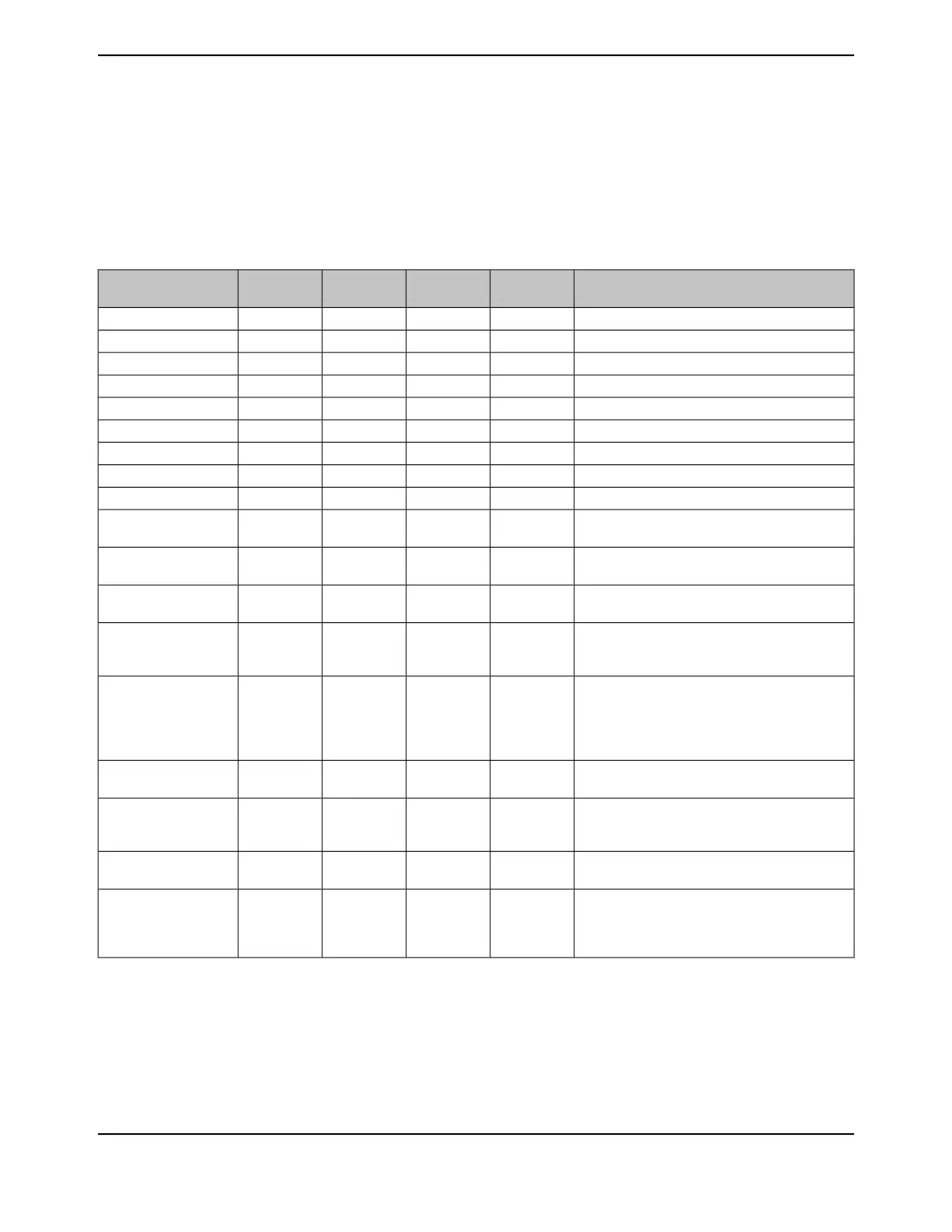
Table 21-1. USB Signals (128TQFP)
DescriptionBuffer TypePin TypePin Mux / Pin
Assignment
Pin NumberPin Name
60-MHz clock to the external PHY.TTLOPB3 (14)92USB0CLK
USB data 0.TTLI/OPL0 (14)81USB0D0
USB data 1.TTLI/OPL1 (14)82USB0D1
USB data 2.TTLI/OPL2 (14)83USB0D2
USB data 3.TTLI/OPL3 (14)84USB0D3
USB data 4.TTLI/OPL4 (14)85USB0D4
USB data 5.TTLI/OPL5 (14)86USB0D5
USB data 6.TTLI/OPP5 (14)106USB0D6
USB data 7.TTLI/OPP4 (14)105USB0D7
Indicates that the external PHY is able to accept
data from the USB controller.
TTLOPP3 (14)104USB0DIR
Bidirectional differential data pin (D- per USB
specification) for USB0.
AnalogI/OPL793USB0DM
Bidirectional differential data pin (D+ per USB
specification) for USB0.
AnalogI/OPL694USB0DP
Optionally used in Host mode to control an external
power source to supply power to the USB bus.
TTLOPA6 (5)
PA7 (11)
PD6 (5)
40
41
127
USB0EPEN
This signal senses the state of the USB ID signal.
The USB PHY enables an integrated pull-up, and
an external element (USB connector) indicates the
initial state of the USB controller (pulled down is
the A side of the cable and pulled up is the B side).
AnalogIPB095USB0ID
Asserted by the external PHY to throttle all data
types.
TTLOPP2 (14)103USB0NXT
Optionally used in Host mode by an external power
source to indicate an error state by that power
source.
TTLIPA7 (5)
PD7 (5)
41
128
USB0PFLT
Asserted by the USB controller to signal the end of
a USB transmit packet or register write operation.
TTLOPB2 (14)91USB0STP
This signal is used during the session request
protocol. This signal allows the USB PHY to both
sense the voltage level of VBUS, and pull up VBUS
momentarily during VBUS pulsing.
AnalogI/OPB196USB0VBUS
21.3 Register Map
Table 21-2 on page 1647 lists the registers. All addresses given are relative to the USB base address
of 0x4005.0000. Note that the USB controller clock must be enabled before the registers can be
programmed (see page 393). There must be a delay of 3 system clocks after the USB module clock
is enabled before any USB module registers are accessed.
June 18, 20141646
Texas Instruments-Production Data
Universal Serial Bus (USB) Controller
 Loading...


