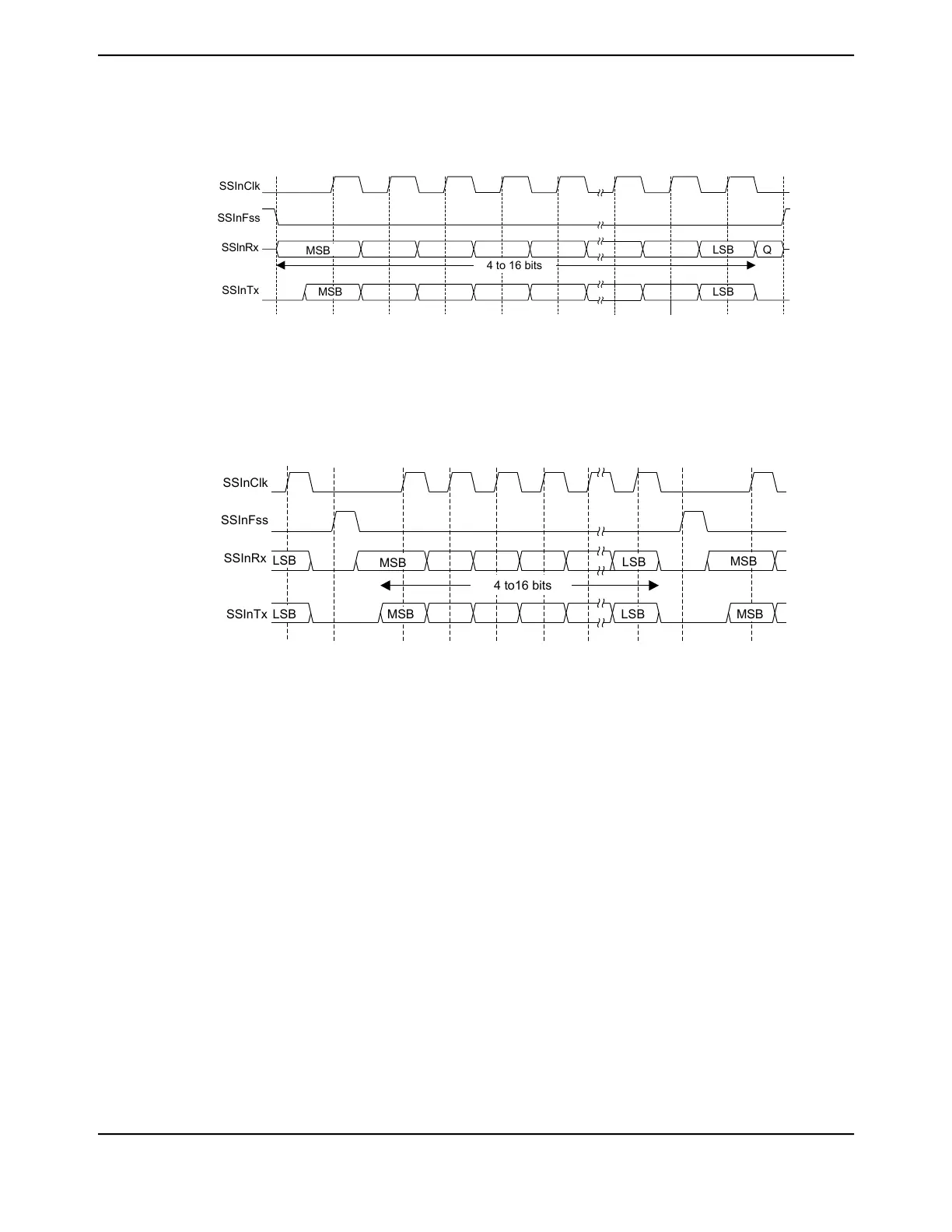
Figure 17-4. Freescale SPI Format (Single Transfer) with SPO=0 and SPH=0
SSInClk
SSInFss
SSInRx
Q
SSInTx
MSB
MSB
LSB
LSB
4 to 16 bits
Note: Q is undefined.
Figure 17-5. Freescale SPI Format (Continuous Transfer) with SPO=0 and SPH=0
SSInClk
SSInFss
SSInRx
LSB
SSInTx MSB LSB
LSB
MSB
MSB
MSB
LSB
4 to16 bits
In this configuration, during idle periods:
■ SSInClk is forced Low
■ SSInFss is forced High
■ The transmit data line SSInDAT0/SSInTX is tristated
■ When the QSSI is configured as a master, it enables the SSInClk pad
■ When the QSSI is configured as a slave, it disables the SSInClk pad
If the QSSI is enabled and valid data is in the transmit FIFO, the start of transmission is signified
by the SSInFss master signal being driven Low, causing slave data to be enabled onto the
SSInDAT1/SSInRX input line of the master. The master SSInDAT0/SSInTX output pad is enabled.
One half SSInClk period later, valid master data is transferred to the SSInDAT0/SSInTX pin.
Once both the master and slave data have been set, the SSInClk master clock pin goes High after
one additional half SSInClk period.
The data is now captured on the rising and propagated on the falling edges of the SSInClk signal.
June 18, 20141236
Texas Instruments-Production Data
Quad Synchronous Serial Interface (QSSI)
 Loading...


