When the PLL is active, the system clock frequency (SysClk) is calculated using the following
equation:
SysClk = f
VCO
/ (PSYSDIV + 1)
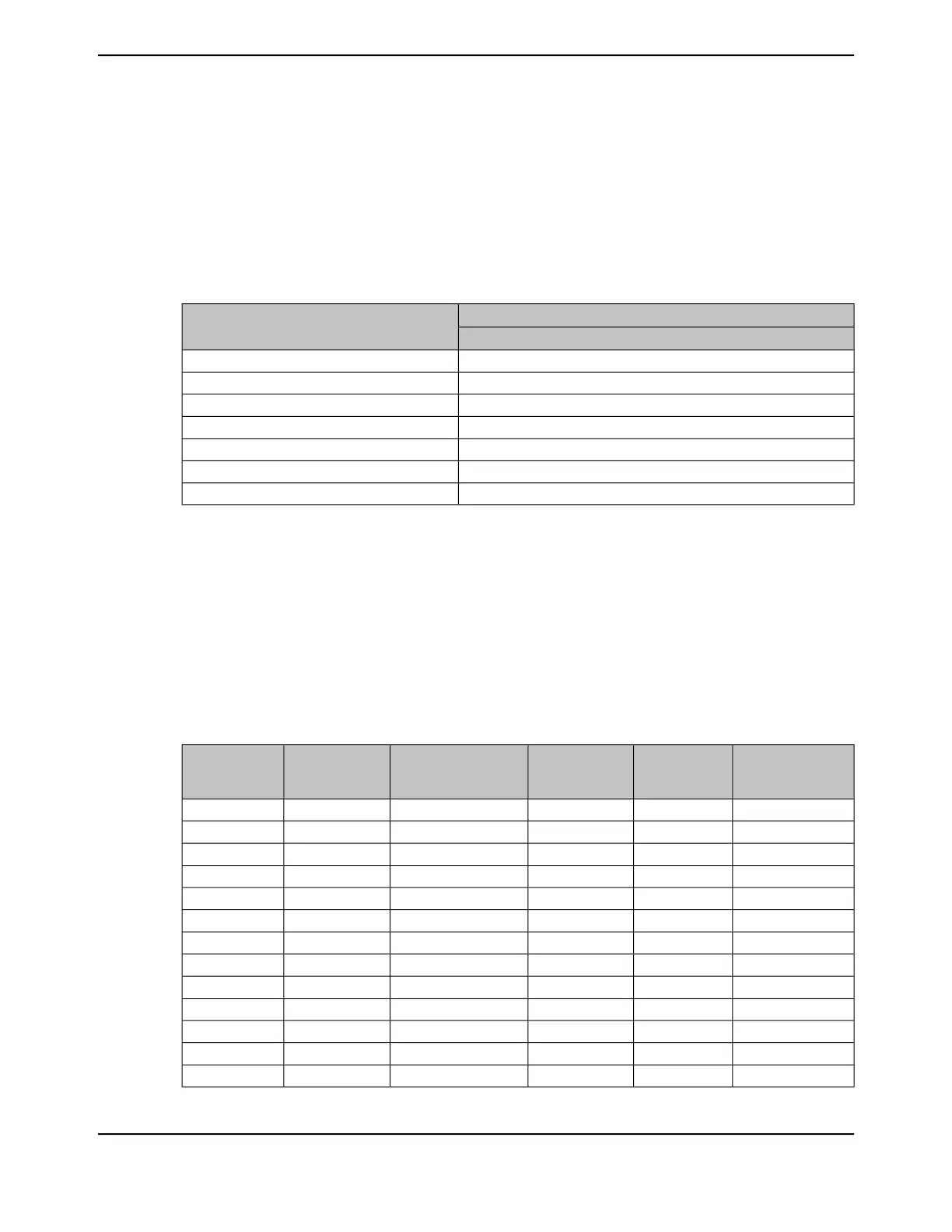
The PLL system divisor factor (PSYSDIV) determines the value of the system clock. Table
5-6 on page 237 shows how the system divisor encodings affect the system clock frequency when
the f
VCO
= 480 MHz.
Table 27-17. System Divisor Factors for f
vco
=480 MHz
f
VCO
(MHz)= 480 MHz
System Clock (SYSCLK) (MHz)
System Divisors (PSYSDIV +1)
a
4120
860
1048
1630
2024
4012
806
a. The use of non-integer divisors introduce additional jitter which may affect interface performance.
If the main oscillator provides the clock reference to the PLL, the translation provided by hardware
and used to program the PLL is available for software in the PLL Frequency n (PLLFREQn) registers
(see page 292). The internal translation provides a translation within ± 1% of the targeted PLL VCO
frequency. Table 5-7 on page 238 shows the actual PLL frequency and error for a given crystal
choice.
Table 5-7 on page 238 provides examples of the programming expected for the PLLFREQ0 and
PLLFREQ1 registers. The first column specifies the input crystal frequency and the last column
displays the PLL frequency given the values of MINT and N, when Q=0.
Table 27-18. Actual PLL Frequency
a
PLL Frequency
(MHz)
Reference
Frequency
(MHz)
b
NMINT (Hexadecimal
Value)
MINT (Decimal
Value)
Crystal
Frequency
(MHz)
32050x00x40645
32020x20x351606
32080x00x28408
320100x00x203210
32040x20x508012
320160x00x142016
32020x80xA016018
320200x00x101620
32080x20x284024
32050x40x406425
48050x00x60965
48060x00x50806
48080x00x3C608
June 18, 20141836
Texas Instruments-Production Data
Electrical Characteristics
 Loading...


