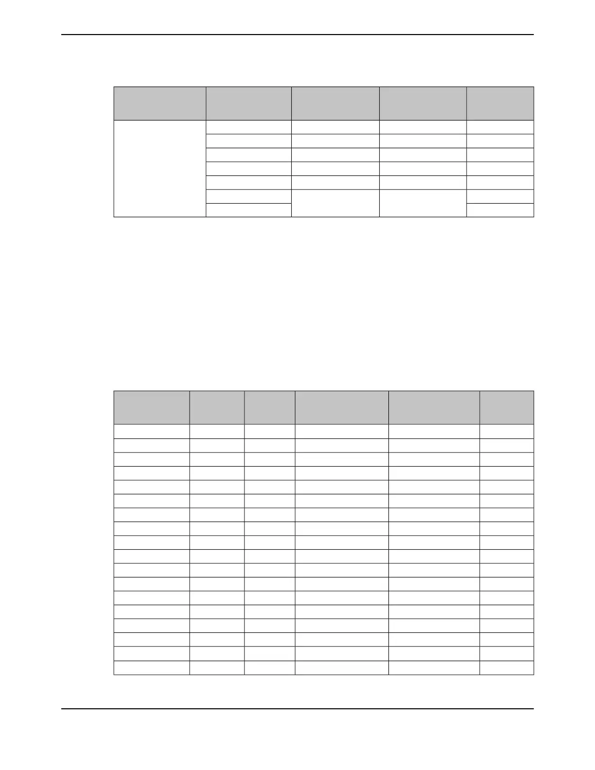
Table 11-8. EPI Host-Bus 8 Signal Connections (continued)
HB8 Signal (MODE
=XFIFO)
HB8 Signal (MODE
=ADNOMUX (Cont.
Read))
HB8 Signal (MODE
=ADMUX)
CSCFGEPI Signal
XXX0x0
EPI0S35
XXX0x1
XXX0x2
XXX0x3
XXX0x4
X
CRECRE
0x5
X0x6
a. "X" indicates the state of this field is a don't care.
b. When an entry straddles several row, the signal configuration is the same for all rows.
c. The clock signal is not required for this mode.
Table 11-9 on page 833 shows how the EPI[31:0] signals function while in Host-Bus 16 mode.
Notice that the signal configuration changes based on the address/data mode selected by the MODE
field in the EPIHB16CFGn register, on the chip select configuration selected by the CSCFG and
CSCFGEXT field in the same register, and on whether byte selects are used as configured by the
BSEL bit in the EPIHB16CFG register.
Although the EPI0S31 signal can be configured for the EPI clock signal in Host-Bus mode, it is not
required and should be configured as a GPIO to reduce EMI in the system. Any unused EPI controller
signals can be used as GPIOs or another alternate function.
Table 11-9. EPI Host-Bus 16 Signal Connections
HB16 Signal
(MODE
=XFIFO)
HB16 Signal (MODE
=ADNOMUX (Cont.
Read))
HB16 Signal (MODE
=ADMUX)
BSELCSCFGEPI Signal
D0D0AD0
b
XX
a
EPI0S0
D1D1AD1XXEPI0S1
D2D2AD2XXEPI0S2
D3D3AD3XXEPI0S3
D4D4AD4XXEPI0S4
D5D5AD5XXEPI0S5
D6D6AD6XXEPI0S6
D7D7AD7XXEPI0S7
D8D8AD8XXEPI0S8
D9D9AD9XXEPI0S9
D10D10AD10XXEPI0S10
D11D11AD11XXEPI0S11
D12D12AD12XXEPI0S12
D13D13AD13XXEPI0S13
D14D14AD14XXEPI0S14
D15D15AD15XXEPI0S15
-A0
b
A16XXEPI0S16
-A1A17XXEPI0S17
833June 18, 2014
Texas Instruments-Production Data
Tiva
™
TM4C1294NCPDT Microcontroller
 Loading...


