20.3.10 Power Management Module
The power management (PMT) module supports the reception of network remote wake-up frames
and AMD Magic Packet™ frames. The PMT module does not perform the clock gate function, but
generates interrupts for remote wake-up frames and magic packets that the MAC receives.
When the application enables the power-down mode in the PMT module by setting the PWRDWN bit
in the Ethernet MAC PMT Control and Status Register (EMACPMTCTLSTAT) register, MAC
offset 0x02C, the MAC drops all received frames and does not forward any frame to the TX/RX
Controller RxFIFO or the application. The MAC comes out of the power-down mode only when a
magic packet or a remote wake-up frame is received and the corresponding detection is enabled.
20.3.10.1 Remote Wake-Up
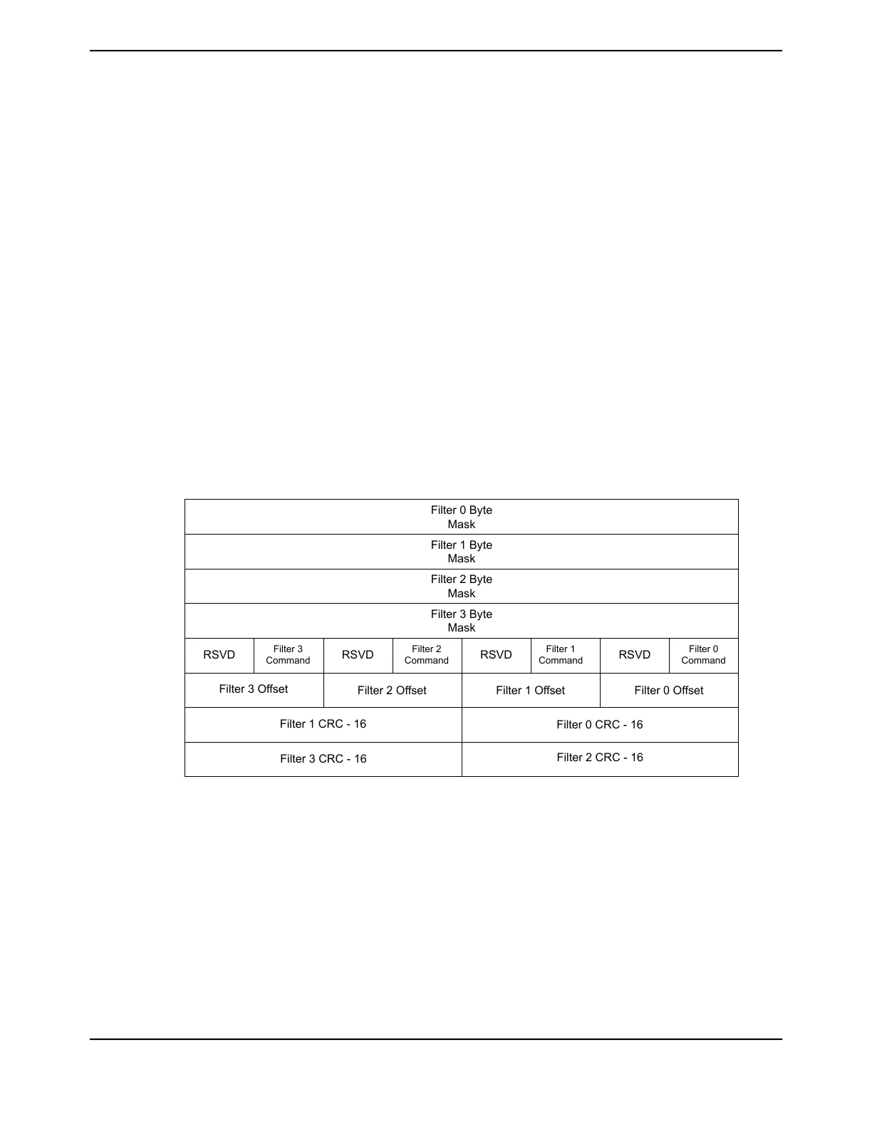
The Remote Wake-Up register bank is made up of eight 32-bit registers. It is loaded by writing the
Ethernet MAC Remote Wake-Up Frame Filter (EMACRWUFF) register eight times. To load values
in the EMACRWUFF register, the entire register must be written. The first write is assigned to register
0 of the bank, then register 1 and so on. The Ethernet MAC Remote Wake-Up Frame Filter
(EMACRWUFF) register is read the same way. The current pointer value of the bank is updated in
the Remote Wake-Up FIFO Pointer (RWKPTR) field of the Ethernet MAC PMT Control and Status
(EMACPMTCTLSTAT) register.
Figure 20-11. Wake-Up Frame Filter Register Bank
Filter 0 Byte
Mask
Filter 1 Byte
Mask
Filter 2 Byte
Mask
Filter 3 Byte
Mask
RSVD
Filter 1
Command
Filter 0
Command
RSVDRSVDRSVD
Filter 3
Command
Filter 2
Command
Filter 3 Offset
Filter 2 Offset Filter 1 Offset Filter 0 Offset
Filter 1 CRC - 16
Filter 0 CRC - 16
Filter 2 CRC - 16
Filter 3 CRC - 16
Filter n Byte Mask
The Filter n Byte Mask registers of the Remote Wake-Up register define the bytes of the frame that
are examined by filter n (0, 1, 2, and 3) in order to determine whether or not a frame is a remote
wake-up frame. The most significant bit (bit 31) of each mask must be zero. Bits [30:0] are the Byte
Mask. If bit, j, of the Byte Mask is set, then the CRC block processes the Filter n Offset + j of the
incoming frame; otherwise Filter n Offset + j is ignored.
Filter n Command
The 4-bit Filter n Command field controls the Filter n operation in the following way:
June 18, 20141454
Texas Instruments-Production Data
Ethernet Controller

 Loading...


