Figure 20-10. Propagation Delay Calculation in Clocks Supporting Peer-to-Peer Path Correction
P2P TC A
Delay
Requester
Time
P2P TC B
Delay
Responder
Time
Pdelay_Req
Pdelay_Resp
t
t
t
t
1
4
3
2
Timestamps
known by Delay
Requester
t
t
1
1
,t
4
1
t
, t
2
, t
3
, t
4
Pdelay_Resp_Follow_Up:
t
2
, t
3
t
BA
t
AB
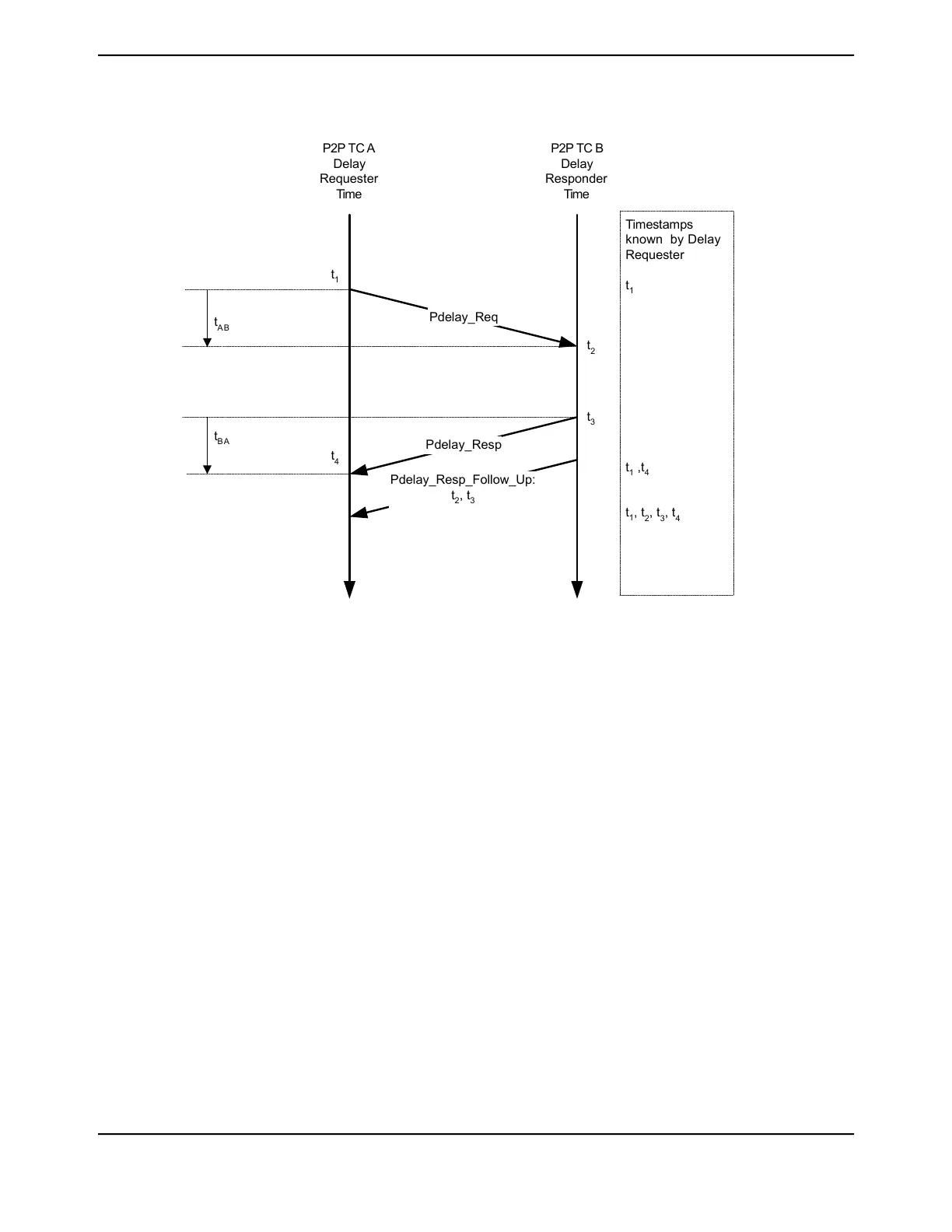
As shown in Figure 20-10 on page 1446, the propagation delay is calculated in the following way:
1. Port-1 issues a Pdelay_Req message and generates a timestamp, t1, for the Pdelay_Req
message.
2. Port-2 receives the Pdelay_Req message and generates a timestamp, t2, for this message.
3. Port-2 returns a Pdelay_Resp message and generates a timestamp, t3, for this message.
To minimize errors because of any frequency offset between the two ports, Port-2 returns the
Pdelay_Resp message as quickly as possible after the receipt of the Pdelay_Req message.
The Port-2 returns any one of the following:
■ The difference between the timestamps t2 and t3 in the Pdelay_Resp message.
■ The difference between the timestamps t2 and t3 in the Pdelay_Resp_Follow_Up message.
■ The timestamps t2 and t3 in the Pdelay_Resp and Pdelay_Resp_Follow_Up messages
respectively.
4. Port-1 generates a timestamp, t4, on receiving the Pdelay_Resp message.
5. Port-1 uses all four timestamps to compute the mean link delay.
Advanced Timestamp Supported Clock Types
The Advance Timestamp Module supports an ordinary clock as defined by the IEEE 1588-2008
standard. The characteristics of this clock is as follows:
June 18, 20141446
Texas Instruments-Production Data
Ethernet Controller
 Loading...


