subsystem to fill the next, least-recently used prefetch buffer. Two memory banks are read in parallel
to retrieve 256-bits worth of data.
If an auto-fill has been started and a miss occurs, the auto-fill completes before the miss is processed.
If an auto-fill occurs that hits the prefetch buffer being processed for the auto-fill, then the ICODE
bus is stalled until the auto fill is complete and new entry can be accessed. For an instruction miss,
access to the flash bank starts immediately after the address is available provided the flash
sub-system is not already processing a DCODE bus access or a PROGRAM/ERASE operation in
the same banks. The target word is passed to the CPU one cycle after it is written to the prefetch
buffer.
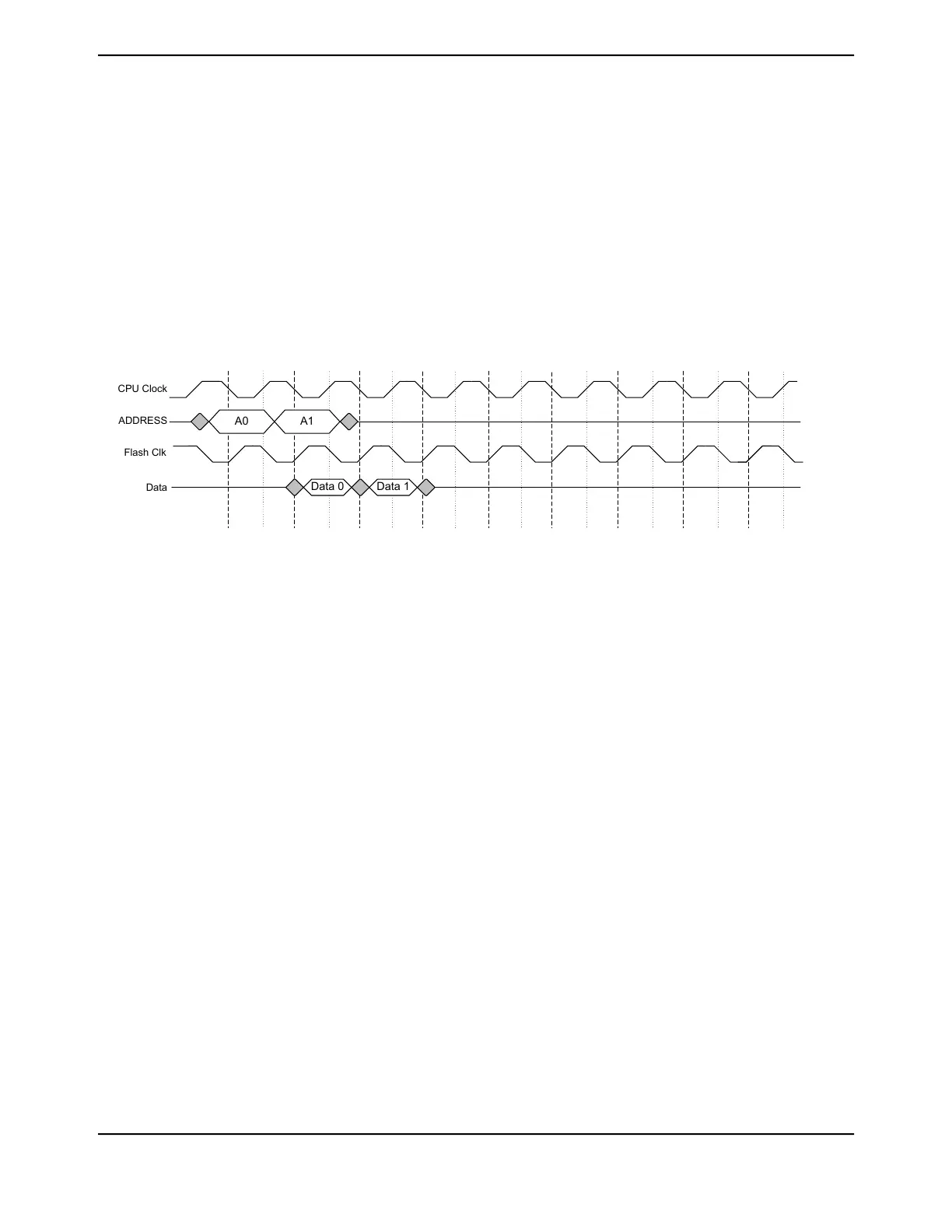
Figure 8-5 on page 607 shows the timing diagram for a hit in the prefetch buffer.
Figure 8-5. Single Cycle Access, 0 Wait States
A0
Data 0 Data 1
CPU Clock
ADDRESS
Flash Clk
Data
A1
The Flash memory can operate at the CPU clock speed with zero-wait-state accesses when data
is resident in the prefetch buffers. When an access does not hit in the prefetch buffer, there is a
delay that is incurred while the data is transferred from the Flash. This delay is dependent on the
programmed CPU frequency. Refer to Table 8-1 on page 605 for required CPU frequency versus
programmed wait-state delay information. Figure 8-6 on page 608 depicts the events that occur as
the CPU steps through the words in the prefetch buffer that has just been loaded until it reaches
the end of the current prefetch line. The notable events are as follows (refer to Figure 8-6 on page 608):
■ EVENT A: When the CPU has a miss in the prefetch buffer, a line is fetched from Flash. The
target word is written to the prefetch buffer and sent to the CPU one cycle after.
■ EVENT B: When the CPU reaches Word 3, the next 256-bit buffer line is fetched, resulting in a
zero-wait-state access of next line's Word 0
■ EVENT C: After this word, if the CPU is still executing sequentially, Word 0 of the next buffer
line that was fetched is sent to the CPU, with zero-wait-state delay
■ EVENT D: Word 0 from the second fetch that occurred is sent to the CPU
607June 18, 2014
Texas Instruments-Production Data
Tiva
™
TM4C1294NCPDT Microcontroller
 Loading...


