Table 9-3. Control Structure Memory Map
ChannelOffset
0, Primary0x0
1, Primary0x10
......
31, Primary0x1F0
0, Alternate0x200
1, Alternate0x210
......
31, Alternate0x3F0
Table 9-4 shows an individual control structure entry in the control table. Each entry is aligned on
a 16-byte boundary. The entry contains four long words: the source end pointer, the destination end
pointer, the control word, and an unused entry. The end pointers point to the ending address of the
transfer and are inclusive. If the source or destination is non-incrementing (as for a peripheral
register), then the pointer should point to the transfer address.
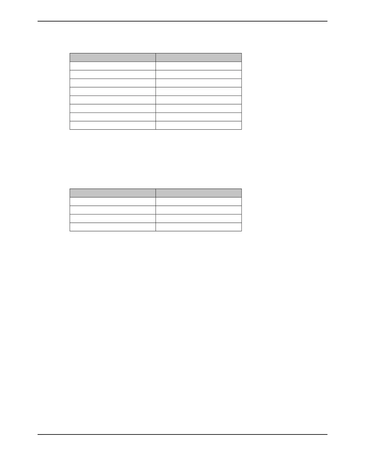
Table 9-4. Channel Control Structure
DescriptionOffset
Source End Pointer0x000
Destination End Pointer0x004
Control Word0x008
Unused0x00C
The control word contains the following fields:
■ Source and destination data sizes
■ Source and destination address increment size
■ Number of transfers before bus arbitration
■ Total number of items to transfer
■ Useburst flag
■ Transfer mode
The control word and each field are described in detail in “μDMA Channel Control
Structure” on page 702. The μDMA controller updates the transfer size and transfer mode fields as
the transfer is performed. At the end of a transfer, the transfer size indicates 0, and the transfer
mode indicates "stopped." Because the control word is modified by the μDMA controller, it must be
reconfigured before each new transfer. The source and destination end pointers are not modified,
so they can be left unchanged if the source or destination addresses remain the same.
Prior to starting a transfer, a μDMA channel must be enabled by setting the appropriate bit in the
DMA Channel Enable Set (DMAENASET) register. A channel can be disabled by setting the
channel bit in the DMA Channel Enable Clear (DMAENACLR) register. At the end of a complete
μDMA transfer, the controller automatically disables the channel.
June 18, 2014684
Texas Instruments-Production Data
Micro Direct Memory Access (μDMA)
 Loading...


