In the case of a single word transmission, after all bits of the data word have been transferred, the
SSInFss line is returned to its idle High state one SSInClk period after the last bit has been
captured.
However, in the case of continuous back-to-back transmissions, the SSInFss signal must be pulsed
High between each data word transfer because the slave select pin freezes the data in its serial
peripheral register and does not allow it to be altered if the SPH bit is clear. Therefore, the master
device must raise the SSInFss pin of the slave device between each data transfer to enable the
serial peripheral data write. On completion of the continuous transfer, the SSInFss pin is returned
to its idle state one SSInClk period after the last bit has been captured.
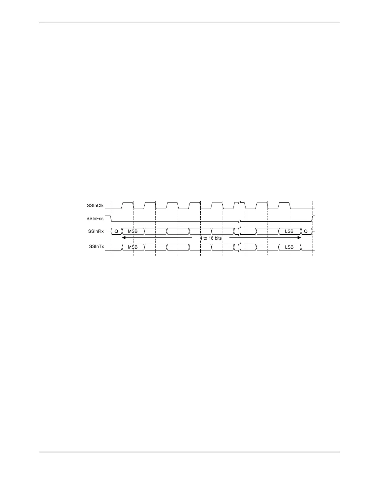
17.3.7.4 Freescale SPI Frame Format with SPO=0 and SPH=1
The transfer signal sequence for Freescale SPI format with SPO=0 and SPH=1 is shown in Figure
17-6 on page 1237, which covers both single and continuous transfers.
Note: This Freescale SPI frame format configuration is only available when operating in Legacy
SSI mode of operation.
Figure 17-6. Freescale SPI Frame Format with SPO=0 and SPH=1
SSInClk
SSInFss
SSInRx
SSInTx
Q
MSB
Q
MSB
LSB
LSB
4 to 16 bits
Q
Note: Q is undefined.
In this configuration, during idle periods:
■ SSInClk is forced Low
■ SSInFss is forced High
■ The transmit data line SSInDAT0/SSInTX is tristated
■ When the QSSI is configured as a master, it enables the SSInClk pad
■ When the QSSI is configured as a slave, it disables the SSInClk pad
If the QSSI is enabled and valid data is in the transmit FIFO, the start of transmission is signified
by the SSInFss master signal being driven Low. The master SSInDAT0/SSInTX output is enabled.
After an additional one-half SSInClk period, both master and slave valid data are enabled onto
their respective transmission lines. At the same time, the SSInClk is enabled with a rising edge
transition.
Data is then captured on the falling edges and propagated on the rising edges of the SSInClk
signal.
1237June 18, 2014
Texas Instruments-Production Data
Tiva
™
TM4C1294NCPDT Microcontroller