■ Ability to determine the elapsed time between the assertion of the timer interrupt and entry into
the interrupt service routine
■ Efficient transfers using Micro Direct Memory Access Controller (µDMA)
– Dedicated channel for each timer
– Burst request generated on timer interrupt
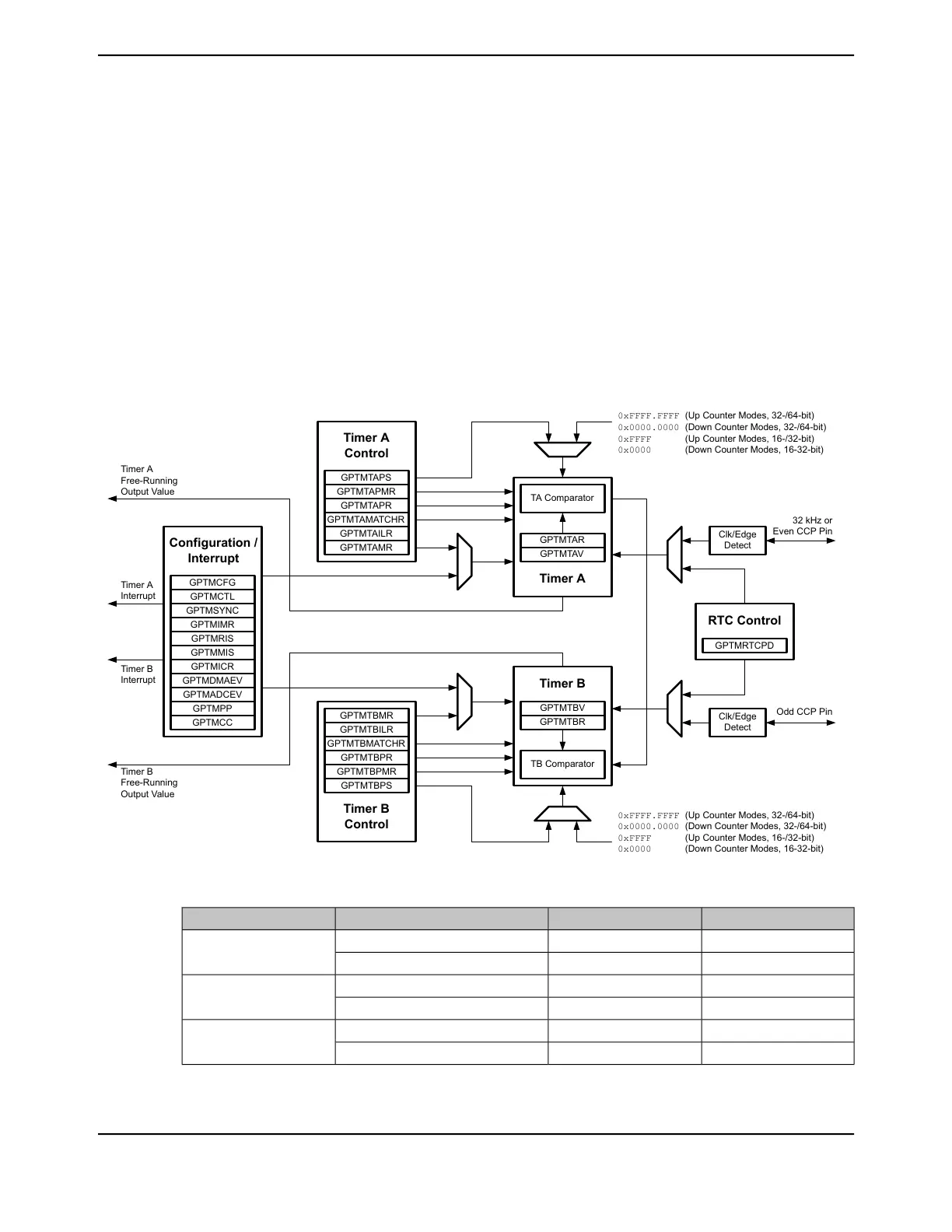
13.1 Block Diagram
In the block diagram, the specific Capture Compare PWM (CCP) pins available depend on the
TM4C1294NCPDT device. See Table 13-1 on page 956 for the available CCP pins and their timer
assignments.
Figure 13-1. GPTM Module Block Diagram
Clk/Edge
Detect
Clk/Edge
Detect
GPTMCFG
Configuration /
Interrupt
GPTMCTL
GPTMSYNC
GPTMRIS
GPTMMIS
GPTMICR
GPTMDMAEV
GPTMIMR
GPTMADCEV
GPTMPP
GPTMCC
GPTMTBPS
Timer B
Control
GPTMTBPMR
GPTMTBPR
GPTMTBMATCHR
GPTMTBILR
GPTMTBMR
GPTMTAPS
Timer A
Control
GPTMTAPMR
GPTMTAPR
GPTMTAMATCHR
GPTMTAILR
GPTMTAMR
GPTMTAV
GPTMTAR
TA Comparator
Timer A
Timer B
GPTMTBV
GPTMTBR
TB Comparator
GPTMRTCPD
RTC Control
Timer A
Interrupt
Timer B
Interrupt
32 kHz or
Even CCP Pin
Odd CCP Pin
Timer A
Free-Running
Output Value
Timer B
Free-Running
Output Value
0xFFFF.FFFF (Up Counter Modes, 32-/64-bit)
0x0000.0000 (Down Counter Modes, 32-/64-bit)
0xFFFF (Up Counter Modes, 16-/32-bit)
0x0000 (Down Counter Modes, 16-32-bit)
0xFFFF.FFFF (Up Counter Modes, 32-/64-bit)
0x0000.0000 (Down Counter Modes, 32-/64-bit)
0xFFFF (Up Counter Modes, 16-/32-bit)
0x0000 (Down Counter Modes, 16-32-bit)
Table 13-1. Available CCP Pins
Odd CCP PinEven CCP PinUp/Down CounterTimer
-T0CCP0Timer A
16/32-Bit Timer 0
T0CCP1-Timer B
-T1CCP0Timer A
16/32-Bit Timer 1
T1CCP1-Timer B
-T2CCP0Timer A
16/32-Bit Timer 2
T2CCP1-Timer B
June 18, 2014956
Texas Instruments-Production Data
General-Purpose Timers
 Loading...


