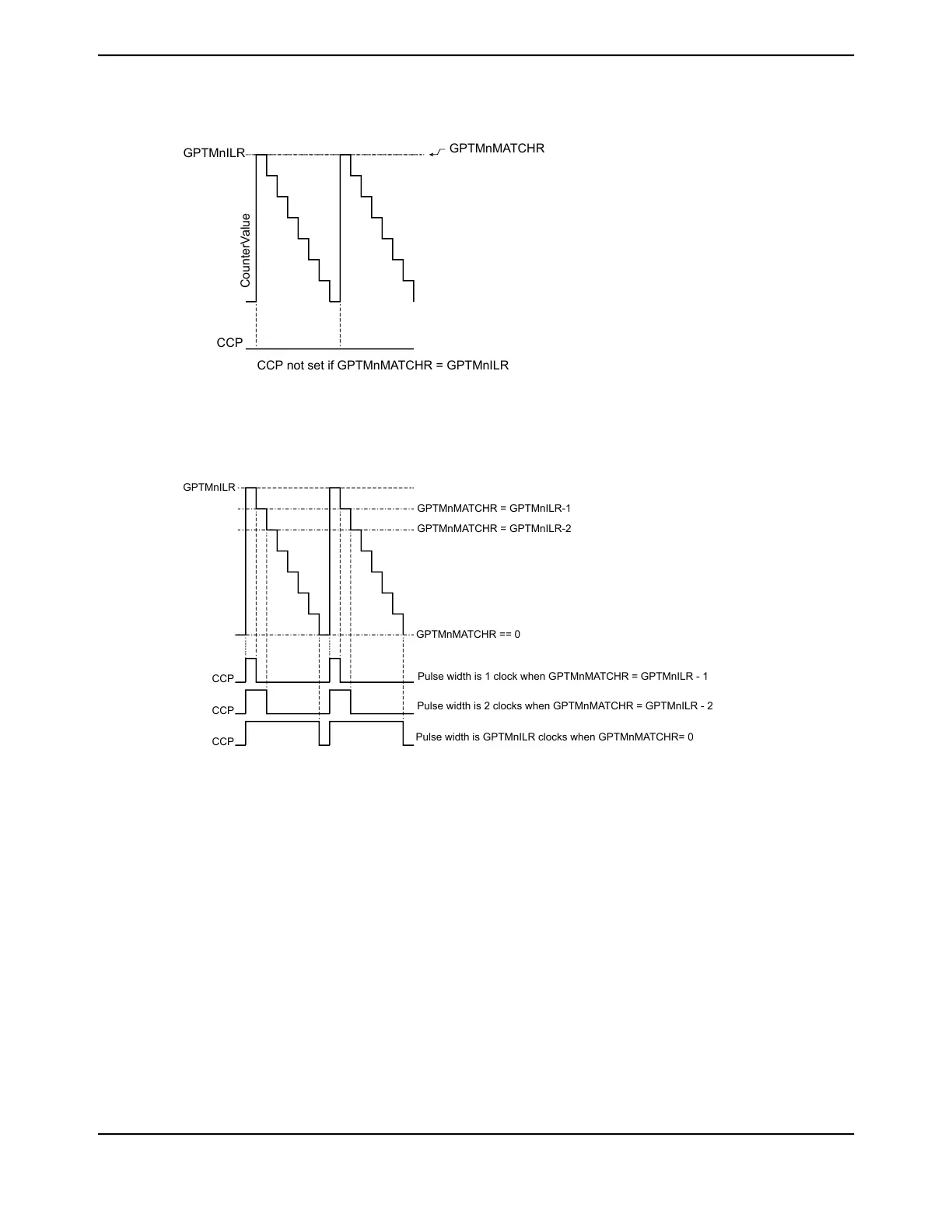
Figure 13-6. CCP Output, GPTMTnMATCHR = GPTMTnILR
CCP
CCP not set if GPTMnMATCHR = GPTMnILR
GPTMnMATCHR
CounterValue
GPTMnILR
Figure 13-7 on page 968 shows how the CCP output operates when the PLO and MRSU bits are set
and the GPTMTnILR is greater than the GPTMTnMATCHR value.
Figure 13-7. CCP Output, GPTMTnILR > GPTMTnMATCHR
GPTMnMATCHR = GPTMnILR-1
GPTMnMATCHR = GPTMnILR-2
GPTMnILR
GPTMnMATCHR == 0
CCP
CCP
CCP
Pulse width is 1 clock when GPTMnMATCHR = GPTMnILR - 1
Pulse width is 2 clocks when GPTMnMATCHR = GPTMnILR - 2
Pulse width is GPTMnILR clocks when GPTMnMATCHR= 0
13.3.4 Wait-for-Trigger Mode
The Wait-for-Trigger mode allows daisy chaining of the timer modules such that once configured,
a single timer can initiate multiple timing events using the Timer triggers. Wait-for-Trigger mode is
enabled by setting the TnWOT bit in the GPTMTnMR register. When the TnWOT bit is set, Timer N+1
does not begin counting until the timer in the previous position in the daisy chain (Timer N) reaches
its time-out event. The daisy chain is configured such that GPTM1 always follows GPTM0, GPTM2
follows GPTM1, and so on. If Timer A is configured as a 32-bit (16/32-bit mode) timer (controlled
by the GPTMCFG field in the GPTMCFG register), it triggers Timer A in the next module. If Timer A
is configured as a 16-bit (16/32-bit mode) timer, it triggers Timer B in the same module, and Timer
B triggers Timer A in the next module. Figure 13-8 on page 969 shows how the GPTMCFG bit affects
the daisy chain. This function is valid for one-shot, periodic, and PWM modes.
Note: If the application requires cyclical daisy-chaining, the TAWOT bit in the GPTMTAMR register
of Timer 0 can be set. In this case, Timer 0 waits for a trigger from the last timer module in
the chain.
June 18, 2014968
Texas Instruments-Production Data
General-Purpose Timers
 Loading...


