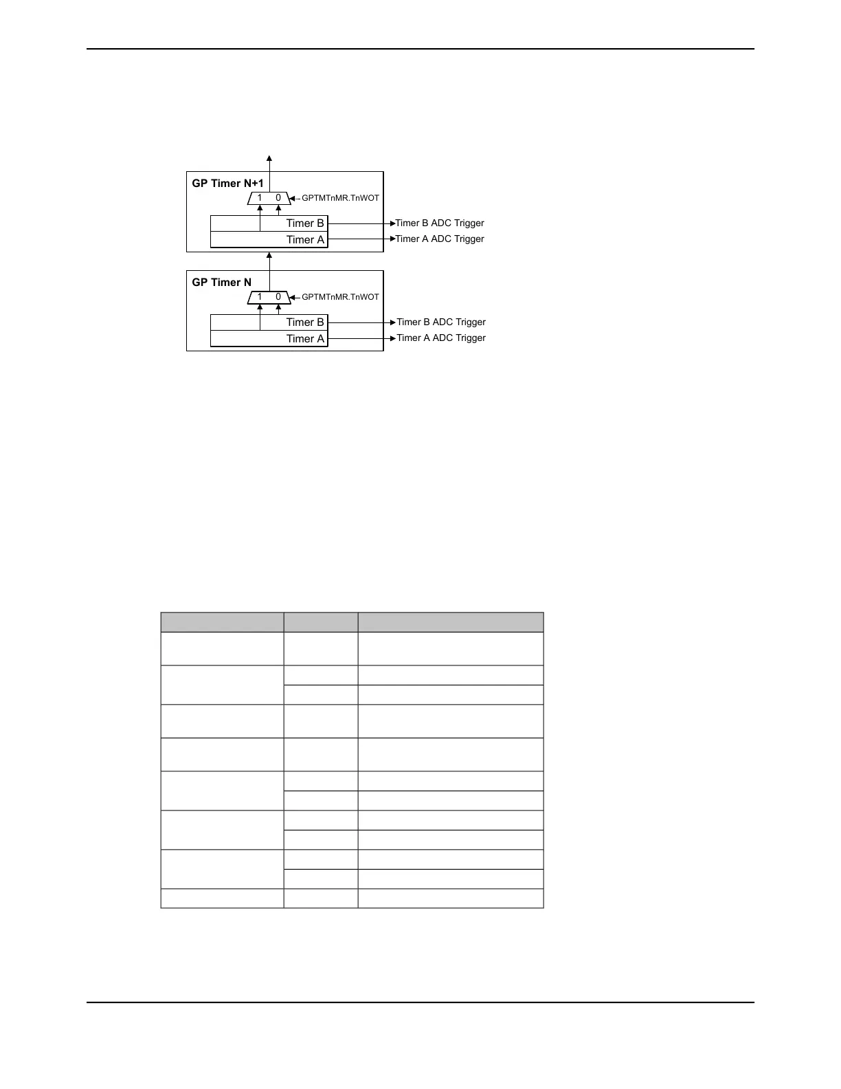
Figure 13-8. Timer Daisy Chain
GP Timer N
Timer B
Timer A
1 0
GP Timer N+1
Timer B
Timer A
1 0
GPTMTnMR.TnWOT
Timer B ADC Trigger
Timer A ADC Trigger
Timer B ADC Trigger
Timer A ADC Trigger
GPTMTnMR.TnWOT
13.3.5 Synchronizing GP Timer Blocks
The GPTM Synchronizer Control (GPTMSYNC) register in the GPTM0 block can be used to
synchronize selected timers to begin counting at the same time. Setting a bit in the GPTMSYNC
register causes the associated timer to perform the actions of a timeout event. An interrupt is not
generated when the timers are synchronized. If a timer is being used in concatenated mode, only
the bit for Timer A must be set in the GPTMSYNC register.
Note: All timers must use the same clock source for this feature to work correctly.
Table 13-10 on page 969 shows the actions for the timeout event performed when the timers are
synchronized in the various timer modes.
Table 13-10. Timeout Actions for GPTM Modes
Time Out ActionCount DirMode
N/A─32-bit One-Shot
(concatenated timers)
Count value = ILRDown32-bit Periodic
(concatenated timers)
Count value = 0Up
Count value = 0Up32-bit RTC
(concatenated timers)
N/A─16- bit One Shot
(individual/split timers)
Count value = ILRDown16-bit Periodic
(individual/split timers)
Count value = 0Up
Count value = ILRDown16-bit Edge-Count
(individual/split timers)
Count value = 0Up
Count value = ILRDown16- bit Edge-Time
(individual/split timers)
Count value = 0Up
Count value = ILRDown16-bit PWM
969June 18, 2014
Texas Instruments-Production Data
Tiva
™
TM4C1294NCPDT Microcontroller
 Loading...


