27.9 Clocks
The following sections provide specifications on the various clock sources and mode.
27.9.1 PLL Specifications
The following tables provide specifications for using the PLL.
Note: If the integrated Ethernet PHY is used in this device, then F
REF_XTAL
and F
REF_EXT
are
required to be 25 MHz.
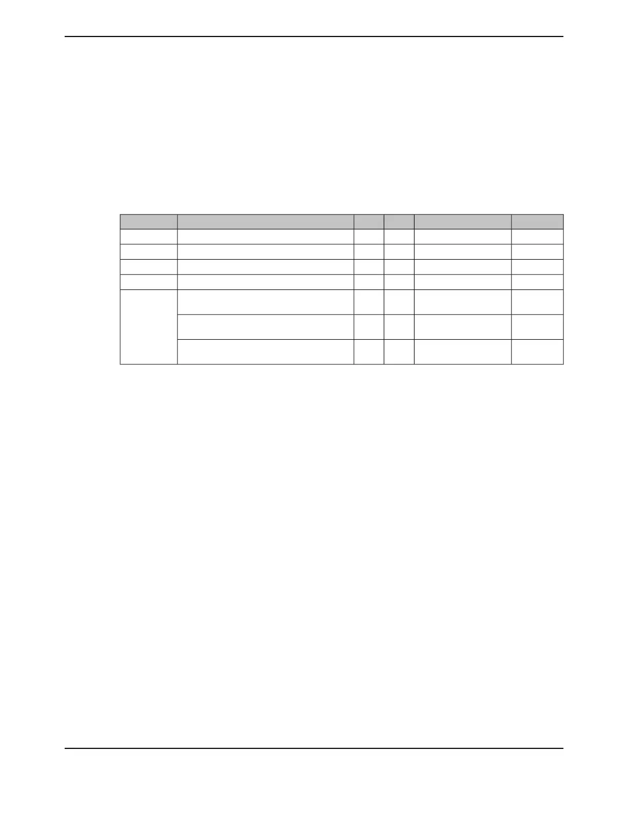
Table 27-16. Phase Locked Loop (PLL) Characteristics
UnitMaxNomMinParameter NameParameter
MHz25-5Crystal referenceF
REF_XTAL
MHz25-5External clock referenceF
REF_EXT
MHz480--PLL VCO frequency at 1.2V
a
F
PLLR
MHz480--PLL VCO frequency at 0.9V
b
F
PLLS
µs512 * (reference clock
period)
--PLL lock time (enabling the PLL) when PLL is
transitioning from power down to power up
T
READY
µs128 * (reference clock
period)
--PLL lock time when the PLL VCO frequency is
changed (PLL is already enabled)
µs128 * (reference clock
period)
--PLL lock time, changing the OSCSRC between
MOSC and PIOSC
a. PLL frequency is manually calculated using the values in the PLLFREQ0 and PLLFREQ1 registers.
b. If the LDO is dropped to 0.9V, the system must be run 1/4 of the maximum frequency at most. The Q value in the PLLFREQ1
register must be set to 0x3 rather than using the PSYSDIV field in the RSCLKCFG register for the divisor.
27.9.1.1 PLL Configuration
The PLL is disabled by default during power-on reset and is enabled later by software if required.
Software specifies the output divisor to set the system clock frequency and enables the PLL to drive
the output. The PLL is controlled using the PLLFREQ0, PLLFREQ1 and PLLSTAT registers.
Changes made to these registers do not become active until after the NEWFREQ bit in the RSCLKCFG
register is enabled.
The clock source for the main PLL is selected by configuring the PLLSRC field in the Run and Sleep
Clock Configuration (RSCLKCFG) register.
The PLL allows for the generation of system clock frequencies in excess of the reference clock
provided. The reference clocks for the PLL are the PIOSC and the MOSC. The PLL is controlled
by two registers, PLLFREQ0 and PLLFREQ1. The PLL VCO frequency (f
VCO
) is determined through
the following calculation:
f
VCO
= f
IN
* MDIV
where
f
IN
= f
XTAL
/(Q+1)(N+1) or f
PIOSC
/(Q+1)(N+1)
MDIV = MINT + (MFRAC / 1024)
The Q and N values are programmed in the PLLFREQ1 register. Note that to reduce jitter, MFRAC
should be programmed to 0x0.
1835June 18, 2014
Texas Instruments-Production Data
Tiva
™
TM4C1294NCPDT Microcontroller
 Loading...


