■ Maskable peripheral requests
■ Interrupt on transfer completion, with a separate interrupt per channel
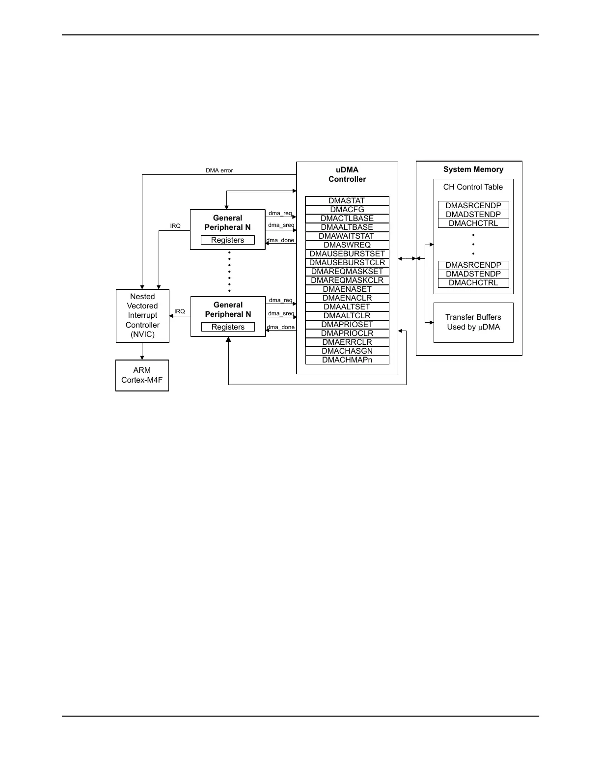
9.1 Block Diagram
Figure 9-1. μDMA Block Diagram
System Memory
CH Control Table
Transfer Buffers
Used by µDMA
uDMA
Controller
•
•
•
DMASRCENDP
DMADSTENDP
DMACHCTRL
DMASRCENDP
DMADSTENDP
DMACHCTRL
DMA error
DMASTAT
DMACFG
DMACTLBASE
DMAALTBASE
DMAWAITSTAT
DMASWREQ
DMAUSEBURSTSET
DMAUSEBURSTCLR
DMAREQMASKSET
DMAREQMASKCLR
DMAENASET
DMAENACLR
DMAALTSET
DMAALTCLR
DMAPRIOSET
DMAPRIOCLR
DMAERRCLR
General
Peripheral N
Registers
Nested
Vectored
Interrupt
Controller
(NVIC)
ARM
Cortex-M4F
IRQ
dma_req
dma_done
DMACHASGN
DMACHMAPn
dma_sreq
General
Peripheral N
Registers
dma_req
dma_done
dma_sreq
IRQ
9.2 Functional Description
The μDMA controller is a flexible and highly configurable DMA controller designed to work efficiently
with the microcontroller's Cortex-M4F processor core. It supports multiple data sizes and address
increment schemes, multiple levels of priority among DMA channels, and several transfer modes
to allow for sophisticated programmed data transfers. The μDMA controller's usage of the bus is
always subordinate to the processor core, so it never holds up a bus transaction by the processor.
Because the μDMA controller is only using otherwise-idle bus cycles, the data transfer bandwidth
it provides is essentially free, with no impact on the rest of the system. The bus architecture has
been optimized to greatly enhance the ability of the processor core and the μDMA controller to
efficiently share the on-chip bus, thus improving performance. The optimizations include RAM
striping and peripheral bus segmentation, which in many cases allow both the processor core and
the μDMA controller to access the bus and perform simultaneous data transfers.
Each peripheral function that is supported has a dedicated channel on the μDMA controller that can
be configured independently. The μDMA controller implements a unique configuration method using
channel control structures that are maintained in system memory by the processor. While simple
transfer modes are supported, it is also possible to build up sophisticated "task" lists in memory that
allow the μDMA controller to perform arbitrary-sized transfers to and from arbitrary locations as part
of a single transfer request. The μDMA controller also supports the use of ping-pong buffering to
accommodate constant streaming of data to or from a peripheral.
Each channel also has a configurable arbitration size. The arbitration size is the number of items
that are transferred in a burst before the μDMA controller re-arbitrates for channel priority. Using
679June 18, 2014
Texas Instruments-Production Data
Tiva
™
TM4C1294NCPDT Microcontroller
 Loading...


