Table 22-1. Analog Comparators Signals (128TQFP) (continued)
DescriptionBuffer TypePin TypePin Mux / Pin
Assignment
Pin NumberPin Name
Analog comparator 0 negative input.AnalogIPC722C0-
Analog comparator 0 output.TTLOPD0 (5)
PL2 (5)
1
83
C0o
Analog comparator 1 positive input.AnalogIPC524C1+
Analog comparator 1 negative input.AnalogIPC425C1-
Analog comparator 1 output.TTLOPD1 (5)
PL3 (5)
2
84
C1o
Analog comparator 2 positive input.AnalogIPP0118C2+
Analog comparator 2 negative input.AnalogIPP1119C2-
Analog comparator 2 output.TTLOPD2 (5)3C2o
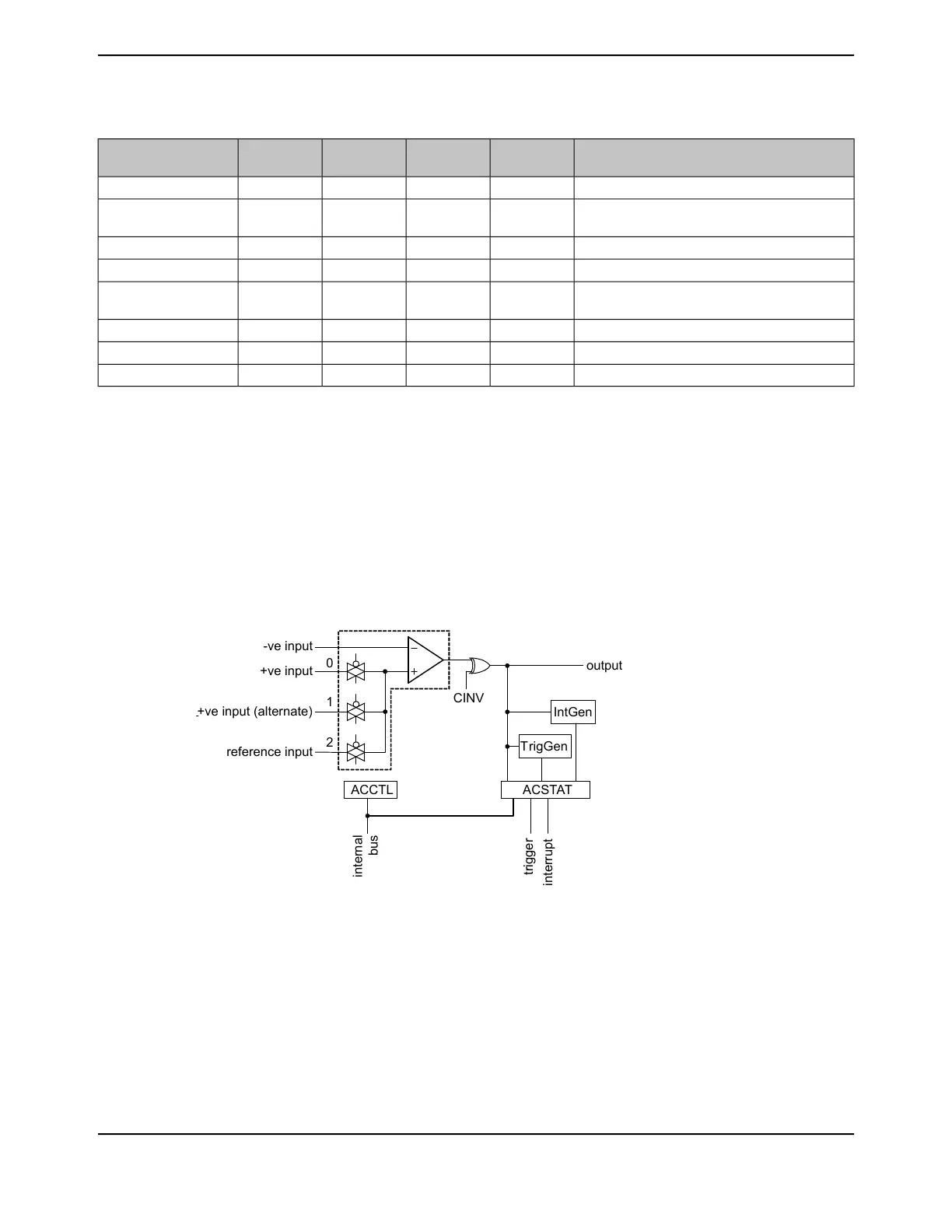
22.3 Functional Description
The comparator compares the VIN- and VIN+ inputs to produce an output, VOUT.
VIN- < VIN+, VOUT = 1
VIN- > VIN+, VOUT = 0
As shown in Figure 22-2 on page 1655, the input source for VIN- is an external input, Cn-, where n
is the analog comparator number. In addition to an external input, Cn+, input sources for VIN+ can
be the C0+ or an internal reference, V
IREF
.
Figure 22-2. Structure of Comparator Unit
ACCTL
CINV
TrigGen
output
ACSTAT
IntGen
1
0
2
reference input
+ve input (alternate)
+ve input
-ve input
internal
bus
interrupt
trigger
A comparator is configured through two status/control registers, Analog Comparator Control
(ACCTL) and Analog Comparator Status (ACSTAT). The internal reference is configured through
one control register, Analog Comparator Reference Voltage Control (ACREFCTL). Interrupt
status and control are configured through three registers, Analog Comparator Masked Interrupt
Status (ACMIS), Analog Comparator Raw Interrupt Status (ACRIS), and Analog Comparator
Interrupt Enable (ACINTEN).
Typically, the comparator output is used internally to generate an interrupt as controlled by the ISEN
bit in the ACCTL register. The output may also be used to drive one of the external pins (Cno), or
generate an analog-to-digital converter (ADC) trigger.
1655June 18, 2014
Texas Instruments-Production Data
Tiva
™
TM4C1294NCPDT Microcontroller
 Loading...


