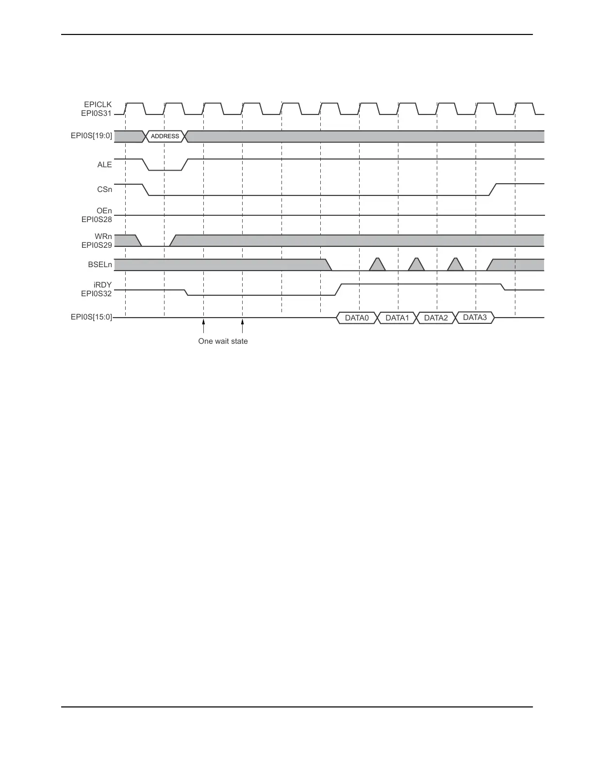
Figure 11-10. Write Delay During Refresh Event
BSELn
ADDRESS
DATA0
DATA1 DATA2
DATA3
EPI0S[19:0]
ALE
CSn
EPICLK
EPI0S31
OEn
EPI0S28
WRn
EPI0S29
iRDY
EPI0S32
EPI0S[15:0]
One wait state
11.4.3.3 Host Bus 16-bit Muxed Interface
Figure 11-11 on page 842 shows how to connect the EPI signals to a 16-bit SRAM and a 16-bit Flash
memory with muxed address and memory using byte selects and dual chip selects with ALE. This
schematic is just an example of how to connect the signals; timing and loading have not been
analyzed. In addition, not all bypass capacitors are shown.
841June 18, 2014
Texas Instruments-Production Data
Tiva
™
TM4C1294NCPDT Microcontroller
 Loading...


