EasyManuals Logo

Texas Instruments TM4C1294NCPDT User Manual

Texas Instruments TM4C1294NCPDT
1890 pages
To Next Page IconTo Next Page
To Previous Page IconTo Previous Page
Page #1771 background imageLoading...
Page #1771 background image
25 Pin Diagram
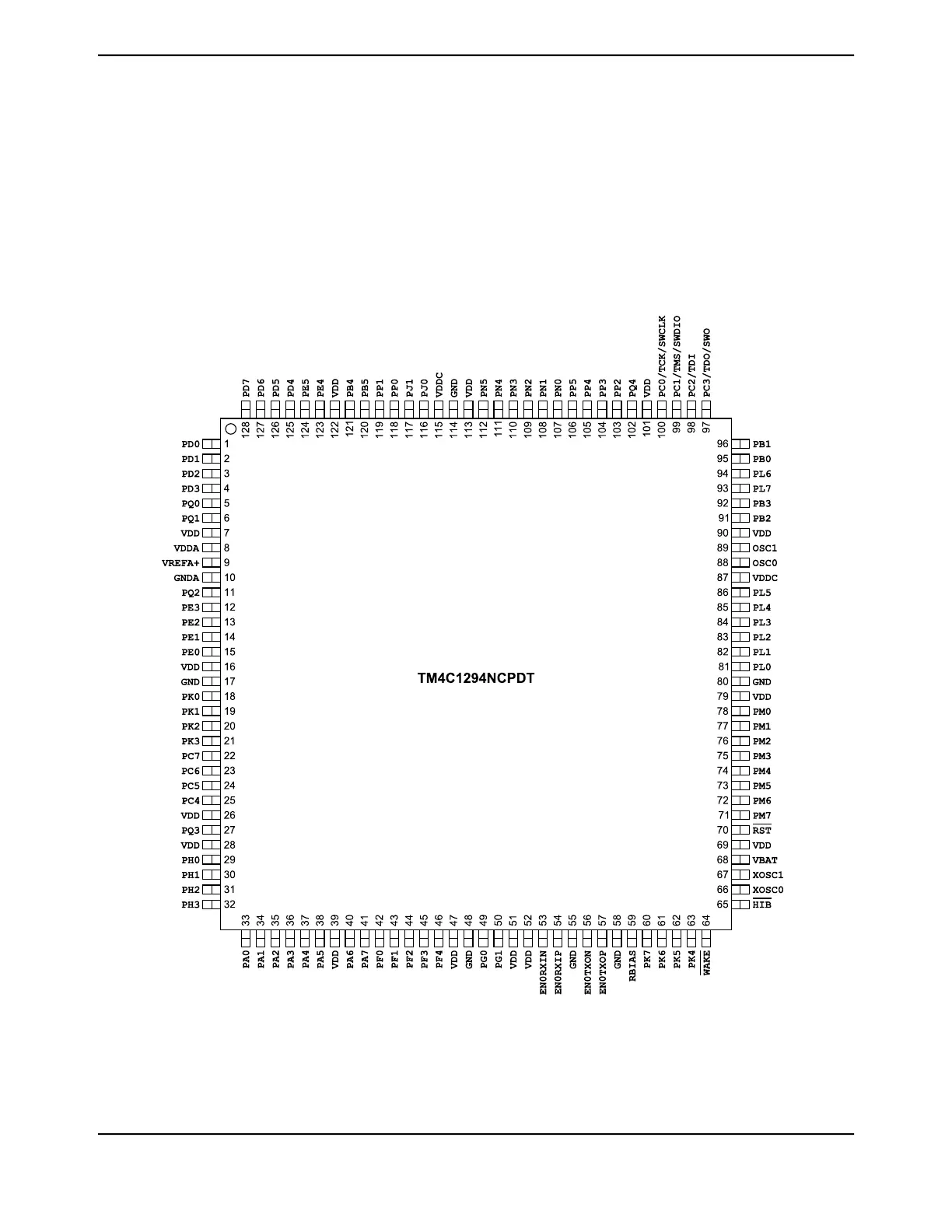
The TM4C1294NCPDT microcontroller pin diagram is shown below.
Each GPIO signal is identified by its GPIO port unless it defaults to an alternate function on reset.
In this case, the GPIO port name is followed by the default alternate function. To see a complete
list of possible functions for each pin, see Table 26-5 on page 1808.
Figure 25-1. 128-Pin TQFP Package Pin Diagram
1771June 18, 2014
Texas Instruments-Production Data
Tiva
TM4C1294NCPDT Microcontroller

Table of Contents

Questions and Answers:

Question and Answer IconNeed help?

Do you have a question about the Texas Instruments TM4C1294NCPDT and is the answer not in the manual?

Texas Instruments TM4C1294NCPDT Specifications

General IconGeneral
BrandTexas Instruments
ModelTM4C1294NCPDT
CategoryMicrocontrollers
LanguageEnglish

Related product manuals