27.2 Operating Characteristics
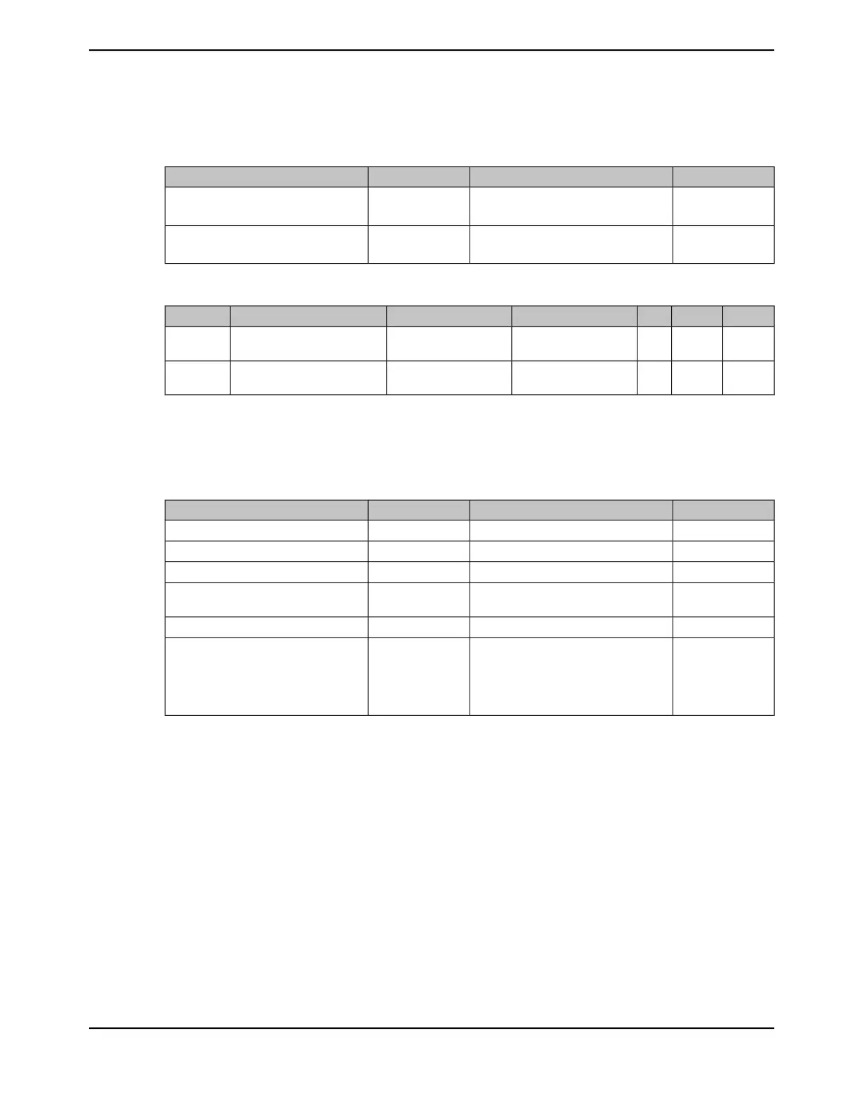
Table 27-3. Temperature Characteristics
UnitValueSymbolCharacteristic
°C-40 to 85 (industrial temperature part)
-40 to 105 (extended temperature part)
T
A
Ambient operating temperature range
°C-40 to 105 (industrial temperature part)
-40 to 125 (extended temperature part)
T
J
Junction operating temperature range
Table 27-4. 128-pin TQFP Power Dissipation
ab
UnitMaxMinT
J
T
A
Parameter NameParameter
mW904-125 °C (industrial
temperature part)
85 °C (industrial
temperature part)
Industrial temperature device
power dissipation
P
DI
mW452-125 °C (extended
temperature part)
105 °C (extended
temperature part)
Extended temperature device
power dissipation
P
DE
a. If the device exceeds the power dissipation value shown, then modifications such as heat sinks or fans must be used to
conform to the limits shown.
b. A larger power dissipation allowance can be achieved by lowering T
A
as long as T
JMAX
shown in Table 27-1 on page 1818
is not exceeded.
Table 27-5. Thermal Characteristics
a
UnitValueSymbolCharacteristic
°C/W44.2Θ
JA
Thermal resistance (junction to ambient)
b
°C/W22.4Θ
JB
Thermal resistance (junction to board)
b
°C/W6.8Θ
JC
Thermal resistance (junction to case)
b
°C/W0.2Ψ
JT
Thermal metric (junction to top of
package)
°C/W22.1Ψ
JB
Thermal metric (junction to board)
°CT
C
+ (P • Ψ
JT
)
c
T
PCB
+ (P • Ψ
JB
)
d
T
A
+ (P • Θ
JA
)
e
T
B
+ (P • Θ
JB
)
fg
T
J
Junction temperature formula
a. For more details about thermal metrics and definitions, see the Semiconductor and IC Package Thermal Metrics Application
Report (literature number SPRA953).
b. Junction to ambient thermal resistance (Θ
JA
), junction to board thermal resistance (Θ
JB
), and junction to case thermal
resistance (Θ
JC
) numbers are determined by a package simulator.
c. T
C
is the case temperature and P is the device power consumption.
d. T
PCB
is the temperature of the board acquired by following the steps listed in the EAI/JESD 51-8 standard summarized
in the Semiconductor and IC Package Thermal Metrics Application Report (literature number SPRA953). P is the device
power consumption.
e. Because Θ
JA
is highly variable and based on factors such as board design, chip/pad size, altitude, and external ambient
temperature, it is recommended that equations containing Ψ
JT
and Ψ
JB
be used for best results.
f. T
B
is temperature of the board.
g. Θ
JB
is not a pure reflection of the internal resistance of the package because it includes the resistance of the testing board
and environment. It is recommended that equations containing Ψ
JT
and Ψ
JB
be used for best results.
1819June 18, 2014
Texas Instruments-Production Data
Tiva
™
TM4C1294NCPDT Microcontroller
 Loading...


