Register 3: UART Flag (UARTFR), offset 0x018
The UARTFR register is the flag register. After reset, the TXFF, RXFF, and BUSY bits are 0, and
TXFE and RXFE bits are 1.
Note: Registers that contain bits for modem control or status only apply to the following UARTs:
■ UART0 (modem flow control and modem status)
■ UART1 (modem flow control and modem status)
■ UART2 (modem flow control)
■ UART3 (modem flow control)
■ UART4 (modem flow control)
UART Flag (UARTFR)
UART0 base: 0x4000.C000
UART1 base: 0x4000.D000
UART2 base: 0x4000.E000
UART3 base: 0x4000.F000
UART4 base: 0x4001.0000
UART5 base: 0x4001.1000
UART6 base: 0x4001.2000
UART7 base: 0x4001.3000
Offset 0x018
Type RO, reset 0x0000.0090
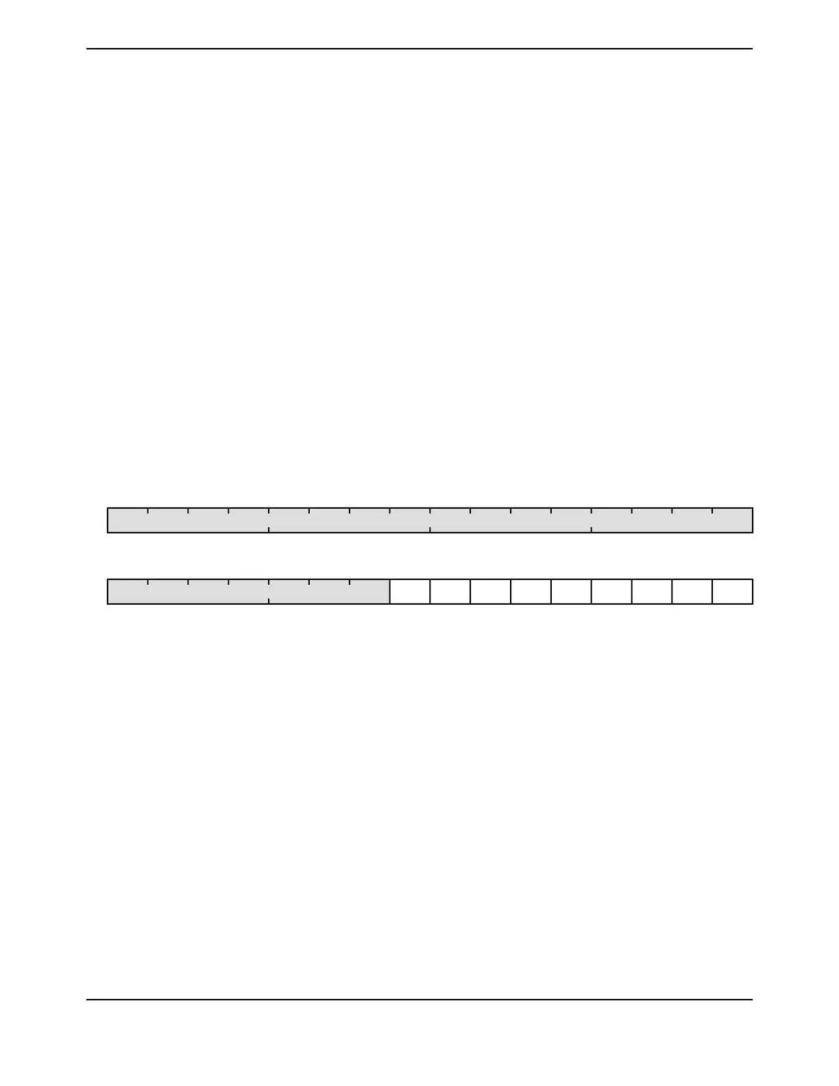
16171819202122232425262728293031
reserved
ROROROROROROROROROROROROROROROROType
0000000000000000Reset
0123456789101112131415
CTSDSRDCDBUSYRXFETXFFRXFFTXFERIreserved
ROROROROROROROROROROROROROROROROType
0000100100000000Reset
DescriptionResetTypeNameBit/Field
Software should not rely on the value of a reserved bit. To provide
compatibility with future products, the value of a reserved bit should be
preserved across a read-modify-write operation.
0x0000.00ROreserved31:9
Ring Indicator
DescriptionValue
The UnRI signal is not asserted.0
The UnRI signal is asserted.1
0RORI8
June 18, 20141180
Texas Instruments-Production Data
Universal Asynchronous Receivers/Transmitters (UARTs)
 Loading...


