EasyManuals Logo

Texas Instruments TM4C1294NCPDT User Manual

Texas Instruments TM4C1294NCPDT
1890 pages
To Next Page IconTo Next Page
To Previous Page IconTo Previous Page
Page #1671 background imageLoading...
Page #1671 background image
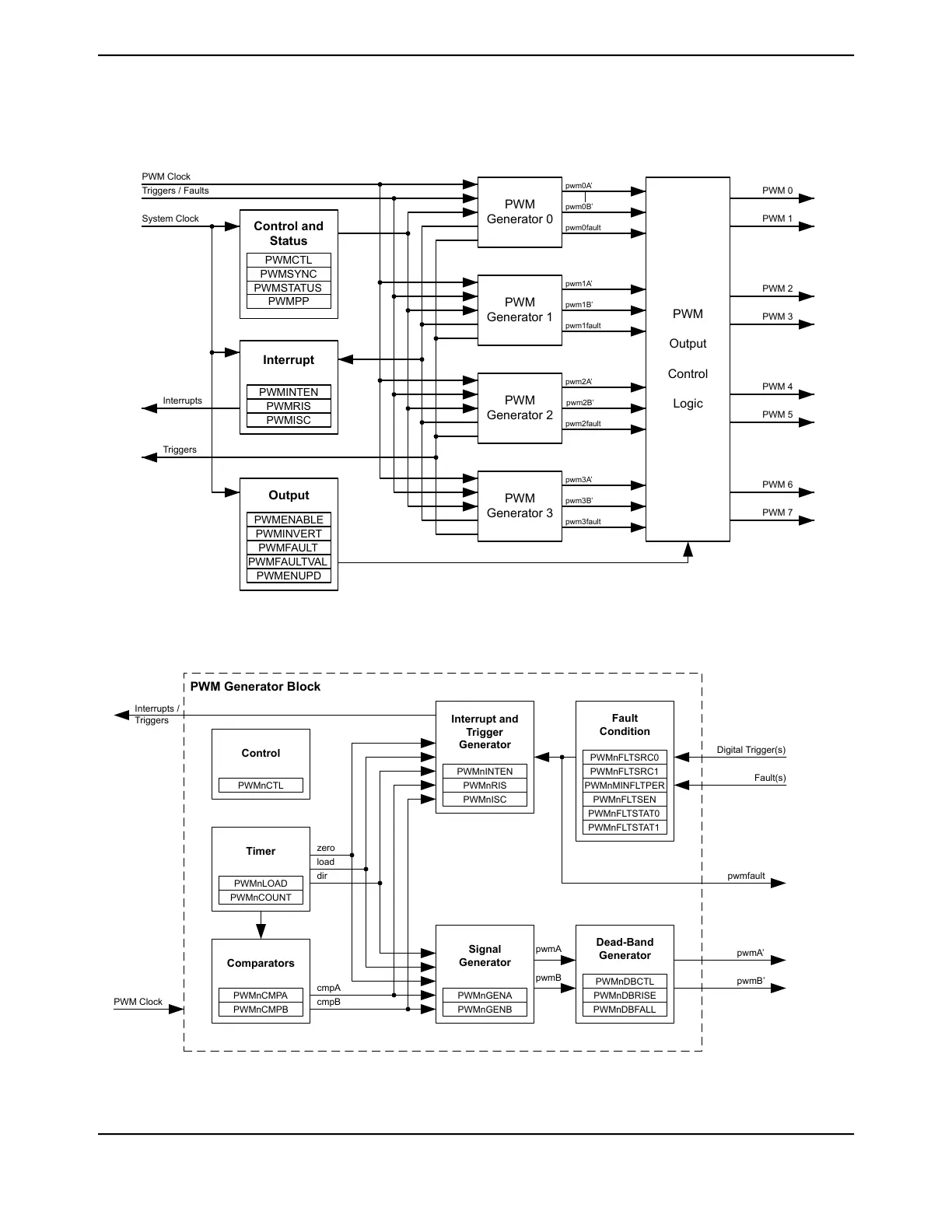
Figure 23-1. PWM Module Diagram
PWM
Generator 0
PWM
Generator 1
PWM
Generator 2
PWM
Generator 3
PWM 0
PWM 1
PWM 2
PWM 3
PWM 4
PWM 5
PWM 6
PWM 7
PWM
Output
Control
Logic
PWM Clock
System Clock
Interrupts
Triggers
pwm0A
pwm0B’
pwm1A
pwm1B’
pwm2A
pwm2B’
pwm3A
pwm3B’
pwm0fault
pwm1fault
pwm2fault
pwm3fault
Triggers / Faults
PWMENABLE
Output
PWMINVERT
PWMFAULT
PWMFAULTVAL
PWMENUPD
PWMINTEN
Interrupt
PWMRIS
PWMISC
PWMCTL
Control and
Status
PWMSYNC
PWMSTATUS
PWMPP
Figure 23-2. PWM Generator Block Diagram
PWMnCMPA
Comparators
PWMnCMPB
PWMnLOAD
Timer
PWMnCOUNT
PWMnDBCTL
Dead-Band
Generator
PWMnDBRISE
PWMnDBFALL
PWMnCTL
Control
PWMnFLTSRC0
Fault
Condition
PWMnFLTSRC1
PWMnMINFLTPER
PWMnFLTSEN
PWMnFLTSTAT0
PWMnFLTSTAT1
PWM Clock
PWM Generator Block
Signal
Generator
PWMnGENA
PWMnGENB
PWMnINTEN
Interrupt and
Trigger
Generator
PWMnRIS
PWMnISC
Digital Trigger(s)
Fault(s)
pwmA
pwmB’
Interrupts /
Triggers
pwmfault
cmpA
cmpB
zero
load
dir
pwmA
pwmB
1671June 18, 2014
Texas Instruments-Production Data
Tiva
TM4C1294NCPDT Microcontroller

Table of Contents

Questions and Answers:

Question and Answer IconNeed help?

Do you have a question about the Texas Instruments TM4C1294NCPDT and is the answer not in the manual?

Texas Instruments TM4C1294NCPDT Specifications

General IconGeneral
BrandTexas Instruments
ModelTM4C1294NCPDT
CategoryMicrocontrollers
LanguageEnglish

Related product manuals