duration of 1.41–2.11 μs (three times the period of IrLPBaud16). The minimum frequency of
IrLPBaud16 ensures that pulses less than one period of IrLPBaud16 are rejected, but pulses
greater than 1.4 μs are accepted as valid pulses.
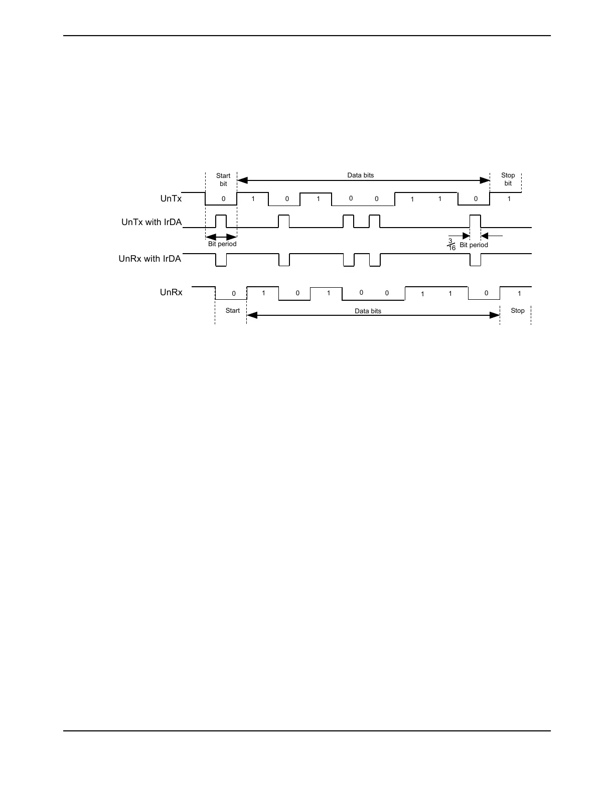
Figure 16-3 on page 1167 shows the UART transmit and receive signals, with and without IrDA
modulation.
Figure 16-3. IrDA Data Modulation
1
0
10
0
0
1
1
0
1
Data bits
1
0
10
0
0
1
1
0
1
Data bits
Start
bit
Start Stop
Bit period
Bit period
3
16
UnTx
UnTx with IrDA
UnRx with IrDA
UnRx
Stop
bit
In both normal and low-power IrDA modes:
■ During transmission, the UART data bit is used as the base for encoding
■ During reception, the decoded bits are transferred to the UART receive logic
The IrDA SIR physical layer specifies a half-duplex communication link, with a minimum 10-ms
delay between transmission and reception. This delay must be generated by software because it
is not automatically supported by the UART. The delay is required because the infrared receiver
electronics might become biased or even saturated from the optical power coupled from the adjacent
transmitter LED. This delay is known as latency or receiver setup time.
16.3.5 ISO 7816 Support
The UART offers basic support to allow communication with an ISO 7816 smartcard. When bit 3
(SMART) of the UARTCTL register is set, the UnTx signal is used as a bit clock, and the UnRx signal
is used as the half-duplex communication line connected to the smartcard. A GPIO signal can be
used to generate the reset signal to the smartcard. The remaining smartcard signals should be
provided by the system design. The maximum clock rate in this mode is system clock / 16.
When using ISO 7816 mode, the UARTLCRH register must be set to transmit 8-bit words (WLEN
bits 6:5 configured to 0x3) with EVEN parity (PEN set and EPS set). In this mode, the UART
automatically uses 2 stop bits, and the STP2 bit of the UARTLCRH register is ignored.
If a parity error is detected during transmission, UnRx is pulled Low during the second stop bit. In
this case, the UART aborts the transmission, flushes the transmit FIFO and discards any data it
contains, and raises a parity error interrupt, allowing software to detect the problem and initiate
retransmission of the affected data. Note that the UART does not support automatic retransmission
in this case.
1167June 18, 2014
Texas Instruments-Production Data
Tiva
™
TM4C1294NCPDT Microcontroller
 Loading...


