27.15 External Peripheral Interface (EPI)
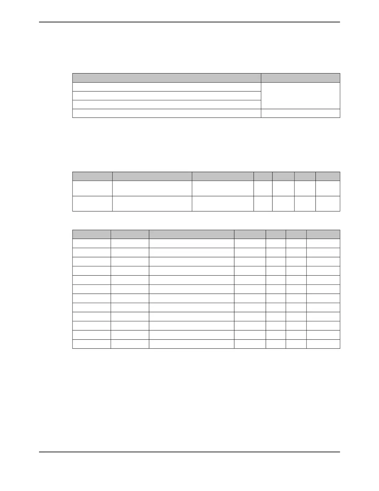
Table 27-38. EPI Interface Load Conditions
Load Value (C
L
)Signals
30 pF
EPI0S[35:0] SDRAM interface
EPI0S[35:0] General-Purpose interface
EPI0S[35:0] Host-Bus interface
40 pFEPI0S[35:0] PSRAM interface
When the EPI module is in SDRAM mode, EPI CLK must be configured to 12 mA. The EPI data
bus can be configured to 8 mA. Table 27-39 on page 1853 shows the rise and fall times in SDRAM
mode. When the EPI module is in Host-Bus or General-Purpose mode, the values in “Input/Output
Pin Characteristics” on page 1849 should be used.
Table 27-39. EPI SDRAM Characteristics
UnitMaxNomMinConditionParameter NameParameter
ns32-12-mA drive, C
L
= 30 pFEPI Rise Time (from 20% to 80% of
V
DD
)
T
SDRAMR
ns32-12-mA drive, C
L
= 30 pFEPI Fall Time (from 80% to 20% of
V
DD
)
T
SDRAMF
Table 27-40. EPI SDRAM Interface Characteristics
a
UnitMaxNomMinParameter NameParameterParameter No
ns--16.67SDRAM Clock periodT
CK
E1
ns--8.33SDRAM Clock high timeT
CH
E2
ns--8.33SDRAM Clock low timeT
CL
E3
ns4--CLK to output validT
COV
E4
ns4--CLK to output invalidT
COI
E5
ns4--CLK to output tristateT
COT
E6
ns--8.5Input set up to CLKT
S
E7
ns--0CLK to input holdT
H
E8
µs--100Power-up timeT
PU
E9
ns--20Precharge all banksT
RP
E10
ns--66Auto refreshT
RFC
E11
EPI CLK--2Program mode registerT
MRD
E12
a. The EPI SDRAM interface must use 12-mA drive.
1853June 18, 2014
Texas Instruments-Production Data
Tiva
™
TM4C1294NCPDT Microcontroller
 Loading...


