Table 27-53. 100Base-TX Transmit Timing (t
R/F
and Jitter) (continued)
UnitMaxNomMinParameter NameParameterParameter No.
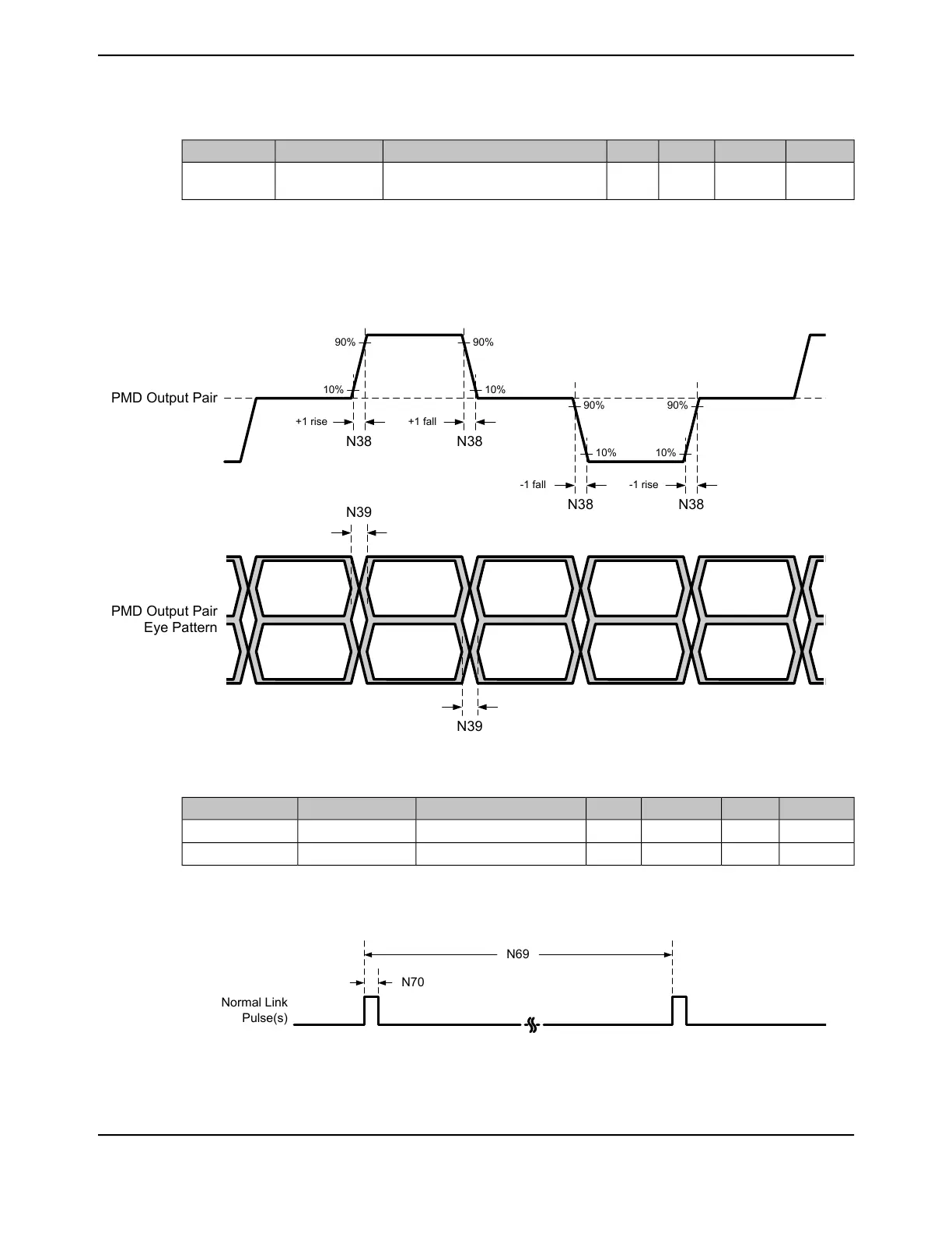
ns1.4--100 Mb/s PMD Output Pair Transmit
Jitter
T
RF_JTTR
N39
a. Rise and fall times taken at 10% and 90% of the +1 or -1 amplitude.
b. Normal mismatch is the difference between the maximum and minimum of all rise and fall times
c. Choice of Ethernet transformer magnetics can affect this parameter.
Figure 27-37. 100 Base-TX Transmit Timing
N39
N39
PMD Output Pair
Eye Pattern
N38
PMD Output Pair
90%
10%
90%
10%
90%
10%
90%
10%
N38
N38 N38
+1 rise +1 fall
-1 fall -1 rise
Table 27-54. 10Base-T Normal Link Pulse Timing
UnitMaxNomMinParameter NameParameterParameter No.
ms-76-Link pulse periodT
LP_PER
N69
µs-100-Link pulse widthT
LP_WID
N70
Figure 27-38. 10Base-TX Normal Link Pulse Timing
N70
Normal Link
Pulse(s)
N69
1873June 18, 2014
Texas Instruments-Production Data
Tiva
™
TM4C1294NCPDT Microcontroller
 Loading...


