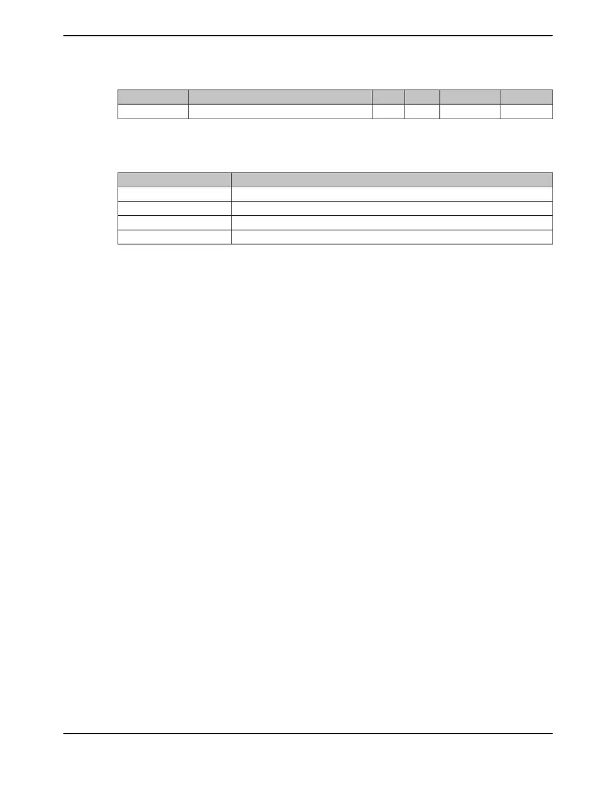
Table 27-9. GPIO Current Restrictions (continued)
UnitMaxNomMinParameter NameParameter
mA80--Cumulative maximum GPIO current per side, top
b
I
MAXT
a. Based on design simulations, not tested in production.
b. Sum of sink and source current for GPIOs as shown in Table 27-10 on page 1822.
Table 27-10. Maximum GPIO Package Side Assignments
GPIOsSide
PC[4-7], PD[0-3], PQ[0-3], PE[0-3], PK[0-3], PN[4-5], PH[0-3]Left
PA[0-7], PF[0-4],PG[0-1], PK[4-7]Bottom
PM[0-7], PL[0-7], PB[0-3]Right
PC[0-3], PQ[4], PP[0-5], PN[0-5], PJ[0-1], PB[4-5], PE[4-5], PD[4-7]Top
I/O Reliability
For typical continuous drive applications, I/O pins configured between 2 mA and 12 mA and operating
at -40 to 85°C, meet the standard 10-year lifetime reliability. If a continuous current sink of 18 mA
is required, then operation is limited to 0 to 75°C in order to meet the standard 10-year reliability.
At 105°C, I/O configured for continuous drive meet the standard 2.5 year lifetime reliability.
In typical switching applications (40% switch rate) operating at -40 to 85°C, all I/O configurations
except 2 mA meet the standard 10-year lifetime reliability with 50-pF loading. By limiting the capacitive
loading to 20 pF for an I/O configured to 2 mA, the 10-year lifetime reliability can be met at -40 to
85°C.
In typical switching applications (40% switch rate) operating at 105°C, all I/O configurations except
2 mA meet the standard 2.5-year lifetime reliability. By reducing the capacitive loading to 20 pF with
a typical switching rate at 105°C, a 2-mA I/O configuration meets a 2.5 year lifetime reliability.
June 18, 20141822
Texas Instruments-Production Data
Electrical Characteristics
 Loading...


