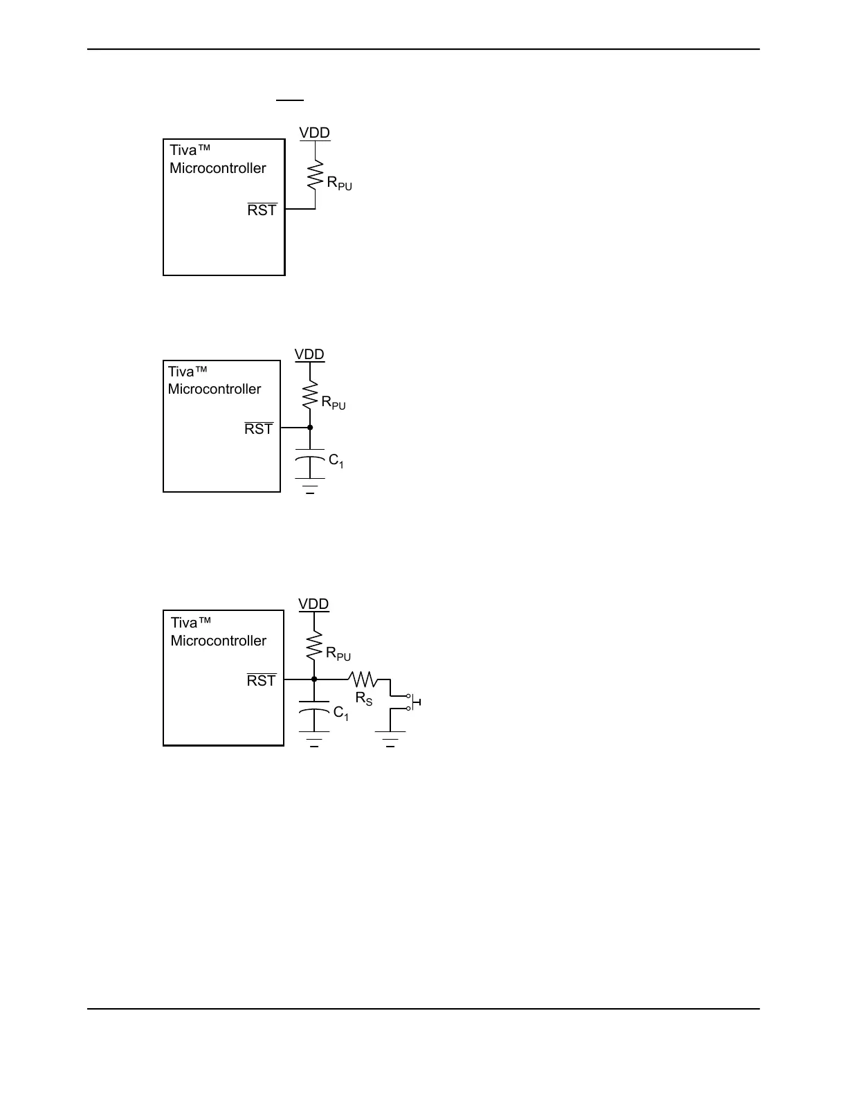
Figure 5-1. Basic RST Configuration
PU
RST
Tiva™
Microcontroller
R
VDD
Note: R
PU
= 0 to 100 kΩ
Figure 5-2. External Circuitry to Extend Power-On Reset
PU
C
1
RST
R
VDD
Tiva™
Microcontroller
Note: R
PU
= 1 kΩ to 100 kΩ
C
1
= 1 nF to 10 µF
Figure 5-3. Reset Circuit Controlled by Switch
PU
C
1
R
S
RST
R
VDD
Tiva™
Microcontroller
Note: Typical R
PU
= 10 kΩ
Typical R
S
= 470 Ω
C
1
= 10 nF
5.2.2.5 Brown-Out Reset (BOR)
The microcontroller provides a brown-out detection circuit that triggers if the V
DD
(external) or V
DDA
(analog) power supply drops below its corresponding brown-out threshold voltage. If a brown-out
condition is detected, the system may generate an interrupt, a system reset or a Power-On Reset.
The default value at reset is to generate an interrupt.
June 18, 2014224
Texas Instruments-Production Data
System Control
 Loading...


