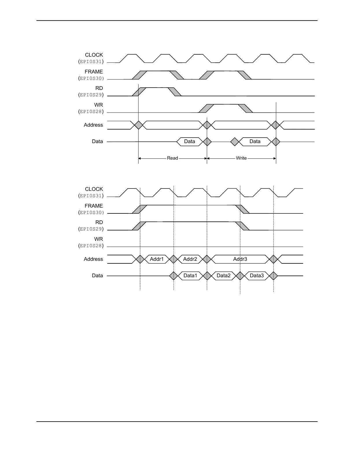
Figure 11-20. Two-Cycle Read, Write Accesses, FRM50=0, FRMCNT=0, WR2CYC=1
Read
Data Data
CLOCK
(EPI0S31)
FRAME
(EPI0S30)
RD
(EPI0S29)
WR
(EPI0S28)
Address
Data
Write
Figure 11-21. Read Accesses, FRM50=0, FRMCNT=0
Addr2
CLOCK
(EPI0S31)
FRAME
(EPI0S30)
RD
(EPI0S29)
WR
(EPI0S28)
Address
Data
Addr1 Addr3
Data2Data1 Data3
FRAME Signal Operation
The operation of the FRAME signal is controlled by the FRMCNT and FRM50 bits. When FRM50 is
clear, the FRAME signal is high whenever the WR or RD strobe is high. When FRMCNT is clear, the
FRAME signal is simply the logical OR of the WR and RD strobes so the FRAME signal is high during
every read or write access, see Figure 11-22 on page 852.
851June 18, 2014
Texas Instruments-Production Data
Tiva
™
TM4C1294NCPDT Microcontroller
 Loading...


