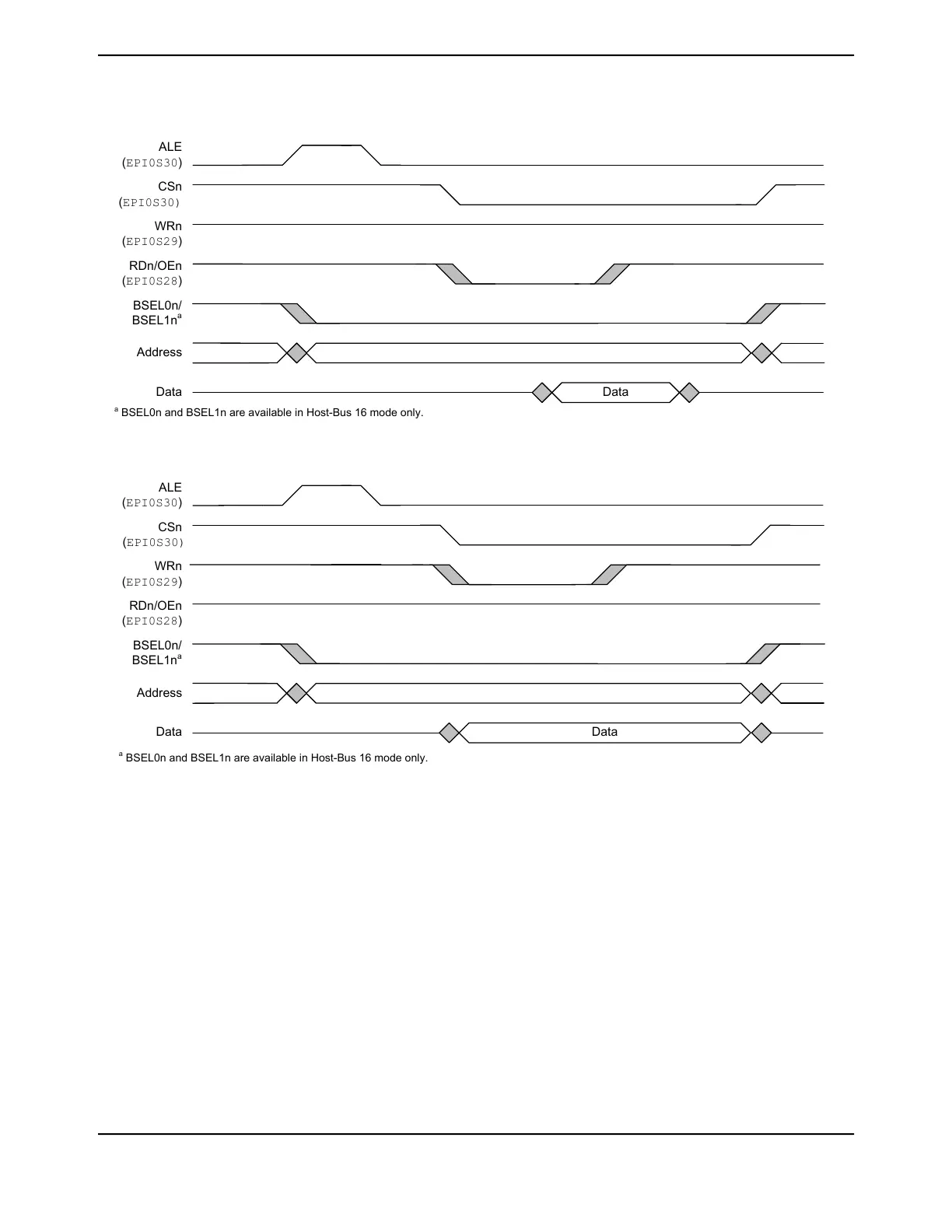
Figure 11-12. Host-Bus Read Cycle, MODE = 0x1, WRHIGH = 0, RDHIGH = 0
Data
ALE
(EPI0S30)
CSn
(EPI0S30)
WRn
(EPI0S29)
RDn/OEn
(EPI0S28)
Address
Data
BSEL0n/
BSEL1n
a
a
BSEL0n and BSEL1n are available in Host-Bus 16 mode only.
Figure 11-13. Host-Bus Write Cycle, MODE = 0x1, WRHIGH = 0, RDHIGH = 0
Data
ALE
(EPI0S30)
CSn
(EPI0S30)
WRn
(EPI0S29)
RDn/OEn
(EPI0S28)
Address
Data
BSEL0n/
BSEL1n
a
a
BSEL0n and BSEL1n are available in Host-Bus 16 mode only.
Figure 11-14 on page 846 shows a write cycle with the address and data signals multiplexed (MODE
field is 0x0 in the EPIHBnCFG register). A read cycle would look similar, with the RDn strobe being
asserted along with CSn and data being latched on the rising edge of RDn.
845June 18, 2014
Texas Instruments-Production Data
Tiva
™
TM4C1294NCPDT Microcontroller
 Loading...


