3. Set bit 7 of the DMA Channel Useburst Clear (DMAUSEBURSTCLR) register to allow the
μDMA controller to respond to single and burst requests.
4. Set bit 7 of the DMA Channel Request Mask Clear (DMAREQMASKCLR) register to allow
the μDMA controller to recognize requests for this channel.
9.3.3.2 Configure the Channel Control Structure
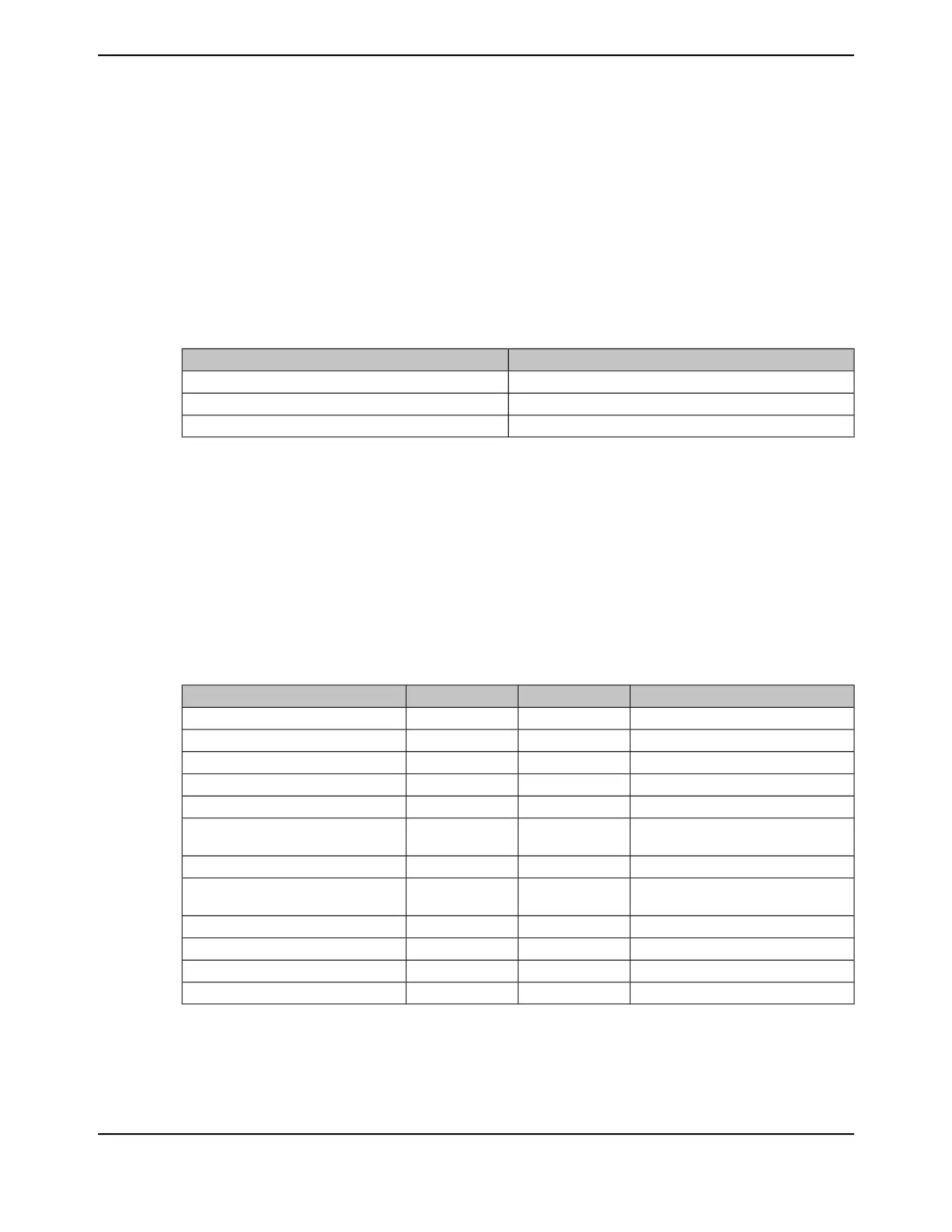
This example transfers 64 bytes from a memory buffer to the peripheral's transmit FIFO register
using μDMA channel 7. The control structure for channel 7 is at offset 0x070 of the channel control
table. The channel control structure for channel 7 is located at the offsets shown in Table 9-9.
Table 9-9. Channel Control Structure Offsets for Channel 7
DescriptionOffset
Channel 7 Source End PointerControl Table Base + 0x070
Channel 7 Destination End PointerControl Table Base + 0x074
Channel 7 Control WordControl Table Base + 0x078
Configure the Source and Destination
The source and destination end pointers must be set to the last address for the transfer (inclusive).
Because the peripheral pointer does not change, it simply points to the peripheral's data register.
1. Program the source end pointer at offset 0x070 to the address of the source buffer + 0x3F.
2. Program the destination end pointer at offset 0x074 to the address of the peripheral's transmit
FIFO register.
The control word at offset 0x078 must be programmed according to Table 9-10.
Table 9-10. Channel Control Word Configuration for Peripheral Transmit Example
DescriptionValueBitsField in DMACHCTL
Destination address does not increment331:30DSTINC
8-bit destination data size029:28DSTSIZE
8-bit source address increment027:26SRCINC
8-bit source data size025:24SRCSIZE
Reserved023:22reserved
Privileged access protection for
destination data writes
021DSTPROT0
Reserved020:19reserved
Privileged access protection for source
data reads
018SRCPROT0
Arbitrates after 4 transfers217:14ARBSIZE
Transfer 64 items6313:4XFERSIZE
N/A for this transfer type03NXTUSEBURST
Use Basic transfer mode12:0XFERMODE
Note: In this example, it is not important if the peripheral makes a single request or a burst request.
Because the peripheral has a FIFO that triggers at a level of 4, the arbitration size is set to
4. If the peripheral does make a burst request, then 4 bytes are transferred, which is what
the FIFO can accommodate. If the peripheral makes a single request (if there is any space
697June 18, 2014
Texas Instruments-Production Data
Tiva
™
TM4C1294NCPDT Microcontroller
 Loading...


