of 0x4 to the GPTM Configuration (GPTMCFG) register (see page 976). In the following sections,
the variable "n" is used in bit field and register names to imply either a Timer A function or a Timer
B function. Throughout this section, the timeout event in down-count mode is 0x0 and in up-count
mode is the value in the GPTM Timer n Interval Load (GPTMTnILR) and the optional GPTM Timer
n Prescale (GPTMTnPR) registers, with the exception of RTC mode.
13.3.3.1 One-Shot/Periodic Timer Mode
The selection of one-shot or periodic mode is determined by the value written to the TnMR field of
the GPTM Timer n Mode (GPTMTnMR) register (see page 977). The timer is configured to count
up or down using the TnCDIR bit in the GPTMTnMR register.
When software sets the TnEN bit in the GPTM Control (GPTMCTL) register (see page 986), the
timer begins counting up from 0x0 or down from its preloaded value. Alternatively, if the TnWOT bit
is set in the GPTMTnMR register, once the TnEN bit is set, the timer waits for a trigger to begin
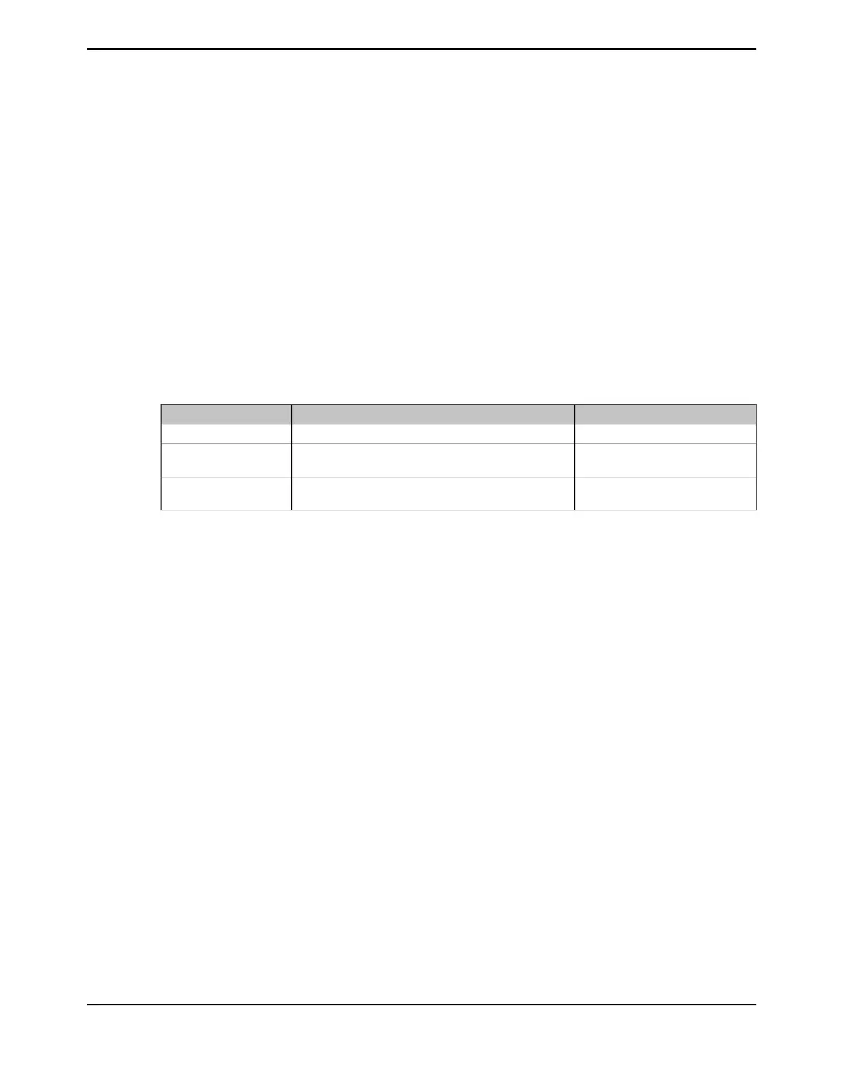
counting (see “Wait-for-Trigger Mode” on page 968). Table 13-4 on page 960 shows the values that
are loaded into the timer registers when the timer is enabled.
Table 13-4. Counter Values When the Timer is Enabled in Periodic or One-Shot Modes
Count Up ModeCount Down ModeRegister
0x0GPTMTnILRGPTMTnR
0x0GPTMTnILR in concatenated mode; GPTMTnPR in
combination with GPTMTnILR in individual mode
GPTMTnV
0x0 in individual mode; not available
in concatenated mode
GPTMTnPR in individual mode; not available in
concatenated mode
GPTMTnPS
When the timer is counting down and it reaches the timeout event (0x0), the timer reloads its start
value from the GPTMTnILR and the GPTMTnPR registers on the next cycle. When the timer is
counting up and it reaches the timeout event (the value in the GPTMTnILR and the optional
GPTMTnPR registers), the timer reloads with 0x0. If configured to be a one-shot timer, the timer
stops counting and clears the TnEN bit in the GPTMCTL register. If configured as a periodic timer,
the timer starts counting again on the next cycle.
In periodic, snap-shot mode (TnMR field is 0x2 and the TnSNAPS bit is set in the GPTMTnMR
register), the value of the timer at the time-out event is loaded into the GPTMTnR register and the
value of the prescaler is loaded into the GPTMTnPS register. The free-running counter value is
shown in the GPTMTnV register. In this manner, software can determine the time elapsed from the
interrupt assertion to the ISR entry by examining the snapshot values and the current value of the
free-running timer. Snapshot mode is not available when the timer is configured in one-shot mode.
In addition to reloading the count value, the GPTM can generate interrupts, CCP outputs and triggers
when it reaches the time-out event. The GPTM sets the TnTORIS bit in the GPTM Raw Interrupt
Status (GPTMRIS) register (see page 996), and holds it until it is cleared by writing the GPTM
Interrupt Clear (GPTMICR) register (see page 1002). If the time-out interrupt is enabled in the GPTM
Interrupt Mask (GPTMIMR) register (see page 993), the GPTM also sets the TnTOMIS bit in the
GPTM Masked Interrupt Status (GPTMMIS) register (see page 999). The time-out interrupt can be
disabled entirely by setting the TnCINTD bit in the GPTM Timer n Mode (GPTMTnMR) register. In
this case, the TnTORIS bit does not even set in the GPTMRIS register.
By setting the TnMIE bit in the GPTMTnMR register, an interrupt condition can also be generated
when the Timer value equals the value loaded into the GPTM Timer n Match (GPTMTnMATCHR)
and GPTM Timer n Prescale Match (GPTMTnPMR) registers. This interrupt has the same status,
masking, and clearing functions as the time-out interrupt, but uses the match interrupt bits instead
(for example, the raw interrupt status is monitored via TnMRIS bit in the GPTM Raw Interrupt Status
June 18, 2014960
Texas Instruments-Production Data
General-Purpose Timers
 Loading...


