the GPTMTnV register holds the free-running timer value. These registers can be read to determine
the time that elapsed between the interrupt assertion and the entry into the ISR.
In addition to generating interrupts, an ADC and/or a μDMA trigger can be generated. The ADC
trigger is enabled by setting the TnOTE bit in GPTMCTL and the event that activates the ADC is
configured in the GPTM ADC Event (GPTMADCEV) register. The μDMA trigger is enabled by
configuring the appropriate μDMA channel as well as the type of trigger selected in the GPTM DMA
Event (GPTMDMAEV) register. See “Channel Configuration” on page 683.
After an event has been captured, the timer does not stop counting. It continues to count until the
TnEN bit is cleared. When the timer reaches the timeout value, it is reloaded with 0x0 in up-count
mode and the value from the GPTMTnILR and GPTMTnPR registers in down-count mode.
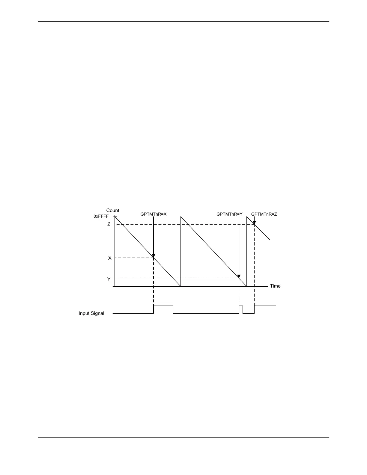
Figure 13-3 on page 965 shows how input edge timing mode works. In the diagram, it is assumed
that the start value of the timer is the default value of 0xFFFF, and the timer is configured to capture
rising edge events.
Each time a rising edge event is detected, the current count value is loaded into the GPTMTnR and
GPTMTnPS registers, and is held there until another rising edge is detected (at which point the new
count value is loaded into the GPTMTnR and GPTMTnPS registers).
Figure 13-3. 16-Bit Input Edge-Time Mode Example
GPTMTnR=Y
Input Signal
Time
Count
GPTMTnR=X GPTMTnR=Z
Z
X
Y
0xFFFF
Note: When operating in Edge-time mode, the counter uses a modulo 2
24
count if prescaler is
enabled or 2
16
, if not. If there is a possibility the edge could take longer than the count, then
another timer configured in periodic-timer mode can be implemented to ensure detection
of the missed edge. The periodic timer should be configured in such a way that:
■ The periodic timer cycles at the same rate as the edge-time timer
■ The periodic timer interrupt has a higher interrupt priority than the edge-time timeout
interrupt.
■ If the periodic timer interrupt service routine is entered, software must check if an
edge-time interrupt is pending and if it is, the value of the counter must be subtracted
by 1 before being used to calculate the snapshot time of the event.
965June 18, 2014
Texas Instruments-Production Data
Tiva
™
TM4C1294NCPDT Microcontroller
 Loading...


