Register 18: UART Clock Configuration (UARTCC), offset 0xFC8
The UARTCC register controls the baud clock source for the UART module. For more information,
see the section called “Peripheral Clock Sources” on page 234.
Note: If the PIOSC is used for the UART baud clock, the system clock frequency must be at least
9 MHz in Run mode.
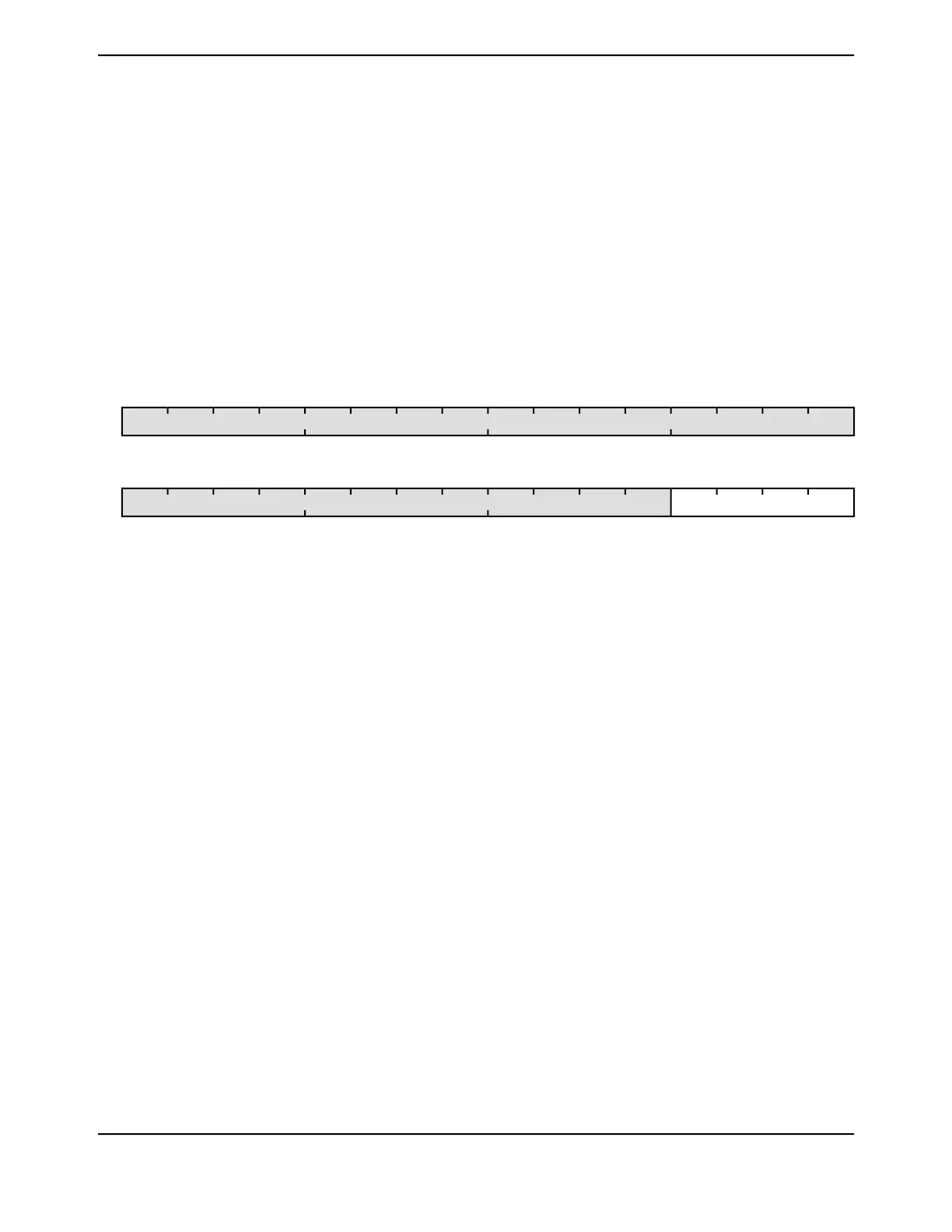
UART Clock Configuration (UARTCC)
UART0 base: 0x4000.C000
UART1 base: 0x4000.D000
UART2 base: 0x4000.E000
UART3 base: 0x4000.F000
UART4 base: 0x4001.0000
UART5 base: 0x4001.1000
UART6 base: 0x4001.2000
UART7 base: 0x4001.3000
Offset 0xFC8
Type RW, reset 0x0000.0000
16171819202122232425262728293031
reserved
ROROROROROROROROROROROROROROROROType
0000000000000000Reset
0123456789101112131415
CSreserved
RWRWRWRWROROROROROROROROROROROROType
0000000000000000Reset
DescriptionResetTypeNameBit/Field
Software should not rely on the value of a reserved bit. To provide
compatibility with future products, the value of a reserved bit should be
preserved across a read-modify-write operation.
0x0000.000ROreserved31:4
UART Baud Clock Source
The following table specifies the source that generates for the UART
baud clock:
DescriptionValue
System clock (based on clock source and divisor factor
programmed in RSCLKCFG register in the System Control
Module)
0x0
reserved0x1-0x4
Alternate clock source as defined by ALTCLKCFG register
in System Control Module.
0x5
Reserved0x5-0xF
0RWCS3:0
1213June 18, 2014
Texas Instruments-Production Data
Tiva
™
TM4C1294NCPDT Microcontroller
 Loading...


