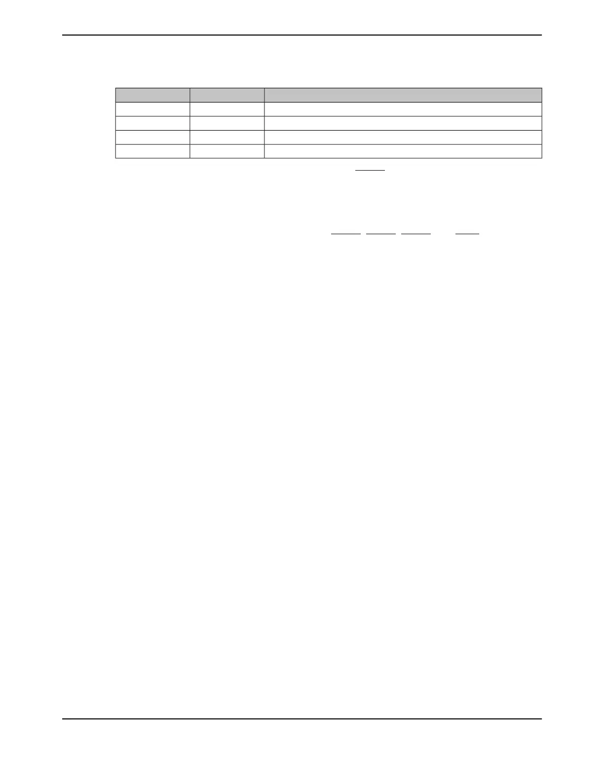
Table 16-2. Flow Control Mode
DescriptionRTSENCTSEN
RTS and CTS flow control enabled11
Only CTS flow control enabled01
Only RTS flow control enabled10
Both RTS and CTS flow control disabled00
Note that when RTSEN is 1, software cannot modify the UnRTS output value through the UARTCTL
register Request to Send (RTS) bit, and the status of the RTS bit should be ignored.
Software Flow Control (Modem Status Interrupts)
Software flow control between two devices is accomplished by using interrupts to indicate the status
of the UART. Interrupts may be generated for the UnDSR, UnDCD, UnCTS, and UnRI signals using
bits 3:0 of the UARTIM register, respectively. The raw and masked interrupt status may be checked
using the UARTRIS and UARTMIS register. These interrupts may be cleared using the UARTICR
register.
16.3.7 9-Bit UART Mode
The UART provides a 9-bit mode that is enabled with the 9BITEN bit in the UART9BITADDR
register. This feature is useful in a multi-drop configuration of the UART where a single master
connected to multiple slaves can communicate with a particular slave through its address or set of
addresses along with a qualifier for an address byte. All the slaves check for the address qualifier
in the place of the parity bit and, if set, then compare the byte received with the preprogrammed
address. If the address matches, then it receives or sends further data. If the address does not
match, it drops the address byte and any subsequent data bytes. If the UART is in 9-bit mode, then
the receiver operates with no parity mode. The address can be predefined to match with the received
byte and it can be configured with the UART9BITADDR register. The matching can be extended
to a set of addresses using the address mask in the UART9BITAMASK register. By default, the
UART9BITAMASK is 0xFF, meaning that only the specified address is matched.
When not finding a match, the rest of the data bytes with the 9th bit cleared are dropped. If a match
is found, then an interrupt is generated to the NVIC for further action. The subsequent data bytes
with the cleared 9th bit are stored in the FIFO. Software can mask this interrupt in case μDMA and/or
FIFO operations are enabled for this instance and processor intervention is not required. All the
send transactions with 9-bit mode are data bytes and the 9th bit is cleared. Software can override
the 9th bit to be set (to indicate address) by overriding the parity settings to sticky parity with odd
parity enabled for a particular byte. To match the transmission time with correct parity settings, the
address byte can be transmitted as a single then a burst transfer. The Transmit FIFO does not hold
the address/data bit, hence software should take care of enabling the address bit appropriately.
16.3.8 FIFO Operation
The UART has two 16x8 FIFOs; one for transmit and one for receive. Both FIFOs are accessed via
the UART Data (UARTDR) register (see page 1175). Read operations of the UARTDR register return
a 12-bit value consisting of 8 data bits and 4 error flags while write operations place 8-bit data in
the transmit FIFO.
Out of reset, both FIFOs are disabled and act as 1-byte-deep holding registers. The FIFOs are
enabled by setting the FEN bit in UARTLCRH (page 1186).
FIFO status can be monitored via the UART Flag (UARTFR) register (see page 1180) and the UART
Receive Status (UARTRSR) register. Hardware monitors empty, full and overrun conditions. The
1169June 18, 2014
Texas Instruments-Production Data
Tiva
™
TM4C1294NCPDT Microcontroller
 Loading...


