2. Enable the μDMA controller by setting the MASTEREN bit of the DMA Configuration (DMACFG)
register.
3. Program the location of the channel control table by writing the base address of the table to the
DMA Channel Control Base Pointer (DMACTLBASE) register. The base address must be
aligned on a 1024-byte boundary.
9.3.2 Configuring a Memory-to-Memory Transfer
μDMA channel 30 is dedicated for software-initiated transfers. However, any channel can be used
for software-initiated, memory-to-memory transfer if the associated peripheral is not being used.
9.3.2.1 Configure the Channel Attributes
First, configure the channel attributes:
1. Program bit 30 of the DMA Channel Priority Set (DMAPRIOSET) or DMA Channel Priority
Clear (DMAPRIOCLR) registers to set the channel to High priority or Default priority.
2. Set bit 30 of the DMA Channel Primary Alternate Clear (DMAALTCLR) register to select the
primary channel control structure for this transfer.
3. Set bit 30 of the DMA Channel Useburst Clear (DMAUSEBURSTCLR) register to allow the
μDMA controller to respond to single and burst requests.
4. Set bit 30 of the DMA Channel Request Mask Clear (DMAREQMASKCLR) register to allow
the μDMA controller to recognize requests for this channel.
9.3.2.2 Configure the Channel Control Structure
Now the channel control structure must be configured.
This example transfers 256 words from one memory buffer to another. Channel 30 is used for a
software transfer, and the control structure for channel 30 is at offset 0x1E0 of the channel control
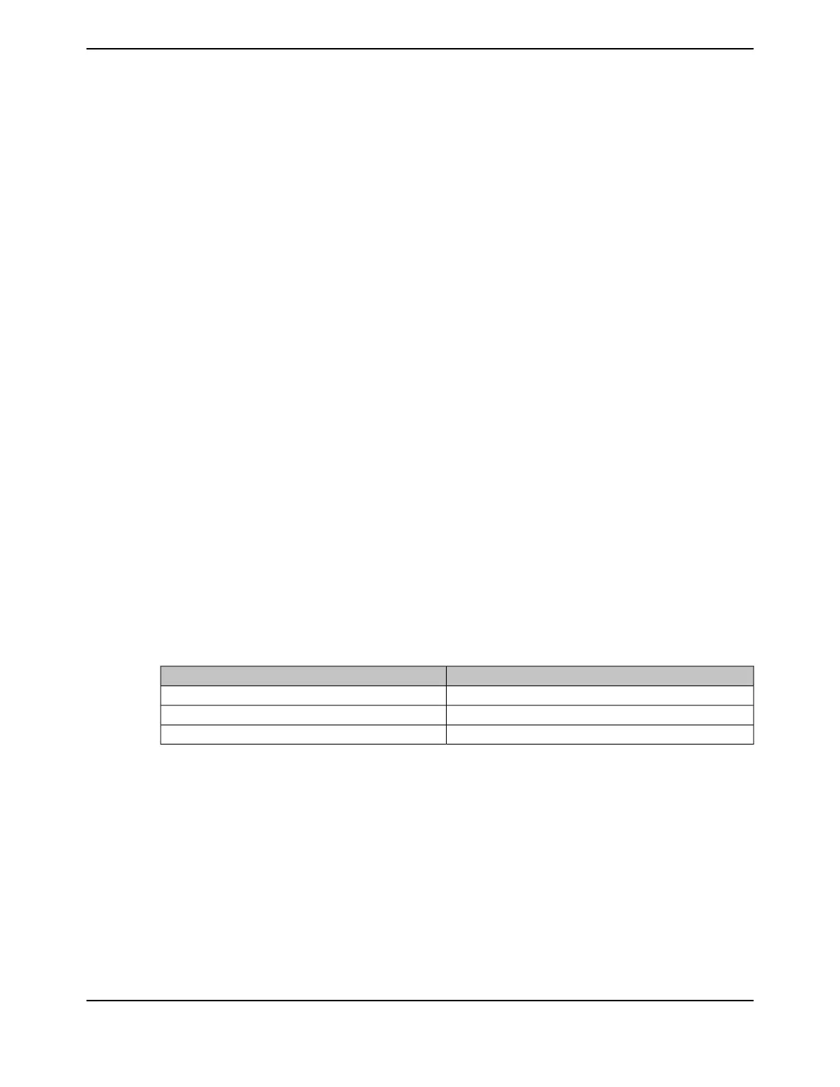
table. The channel control structure for channel 30 is located at the offsets shown in Table 9-7.
Table 9-7. Channel Control Structure Offsets for Channel 30
DescriptionOffset
Channel 30 Source End PointerControl Table Base + 0x1E0
Channel 30 Destination End PointerControl Table Base + 0x1E4
Channel 30 Control WordControl Table Base + 0x1E8
Configure the Source and Destination
The source and destination end pointers must be set to the last address for the transfer (inclusive).
1. Program the source end pointer at offset 0x1E0 to the address of the source buffer + 0x3FC.
2. Program the destination end pointer at offset 0x1E4 to the address of the destination buffer +
0x3FC.
The control word at offset 0x1E8 must be programmed according to Table 9-8.
695June 18, 2014
Texas Instruments-Production Data
Tiva
™
TM4C1294NCPDT Microcontroller
 Loading...


