Table 8-1. MEMTIM0 Register Configuration versus Frequency (continued)
Flash Wait States
(FWS)
Flash Bank
Clock Edge
(FBCE)
Flash Bank Clock
High Time (FBCHT)
Time Period Range (t) in nsCPU Frequency range (f)
in MHz
0x500x610 > t ≥ 8.33100< f ≤120
To update the MEMTIM0 register with the new Flash configuration values, the MEMTIMU bit should
be set in the Run and Sleep Mode Configuration Register (RSCLKCFG), System Control offset
0x0B0.
Note: The associated Flash and EEPROM fields in the MEMTIM0 register must be programmed
to the same values. For example, the FWS field must be programmed to the same value as
the EWS field.
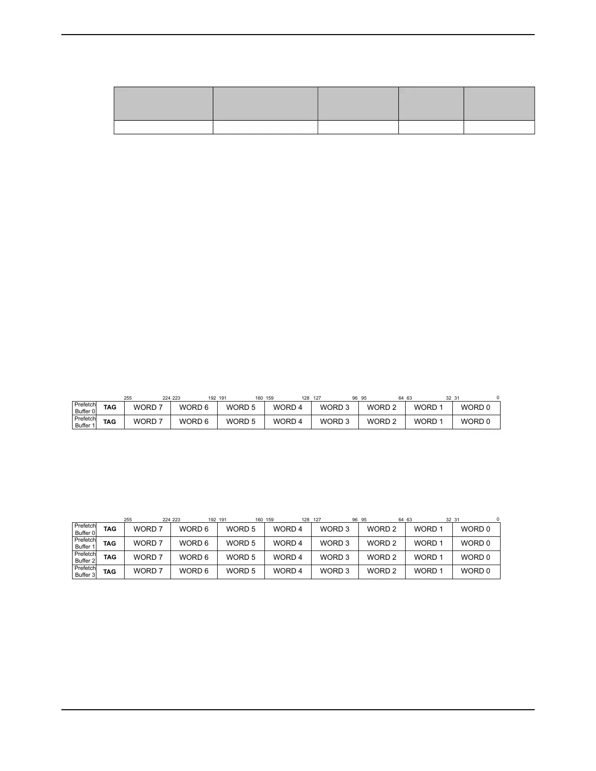
8.2.3.2 Prefetch Buffers
The prefetch buffers can exist as a single set of 2x256-bit buffers or 4x256-bit buffers depending
on the SPFE bit programmed in the Flash Configuration Register (FLASHCONF) register, offset
0xFC8. At reset, all four buffers are enabled. The buffers are filled using a "least-recently-used"
(LRU) method. When operating in a single set buffer configuration, the two, 256-bit buffers create
a deterministic configuration as each "next" write is sent to the previous buffer that was written.
Figure 8-3 on page 606 depicts the single 256-bit buffer set. The single prefetch buffer set should
only be used when the code execution must be purely deterministic for the number of clock cycles
it takes to execute. Utilizing the four prefetch buffer configuration is the preferred method of
configuration.
Figure 8-3. Single 256-Bit Prefetch Buffer Set
WORD 7 WORD 6 WORD 5 WORD 4 WORD 3 WORD 2 WORD 1 WORD 0
WORD 6 WORD 5 WORD 4 WORD 3 WORD 2 WORD 1 WORD 0WORD 7
TAG
Prefetch
Buffer 1
255 127 96 95 64 63 32 31
0
128159160191192223224
Prefetch
Buffer 0
TAG
When the buffers are configured as four, 256-bit buffers, they function as one set, with one of the
four buffers tagged as the LRU and the next to be used when an auto-fill or miss occurs.
Figure 8-4. Four 256-Bit Prefetch Buffer Configuration
WORD 7 WORD 6 WORD 5 WORD 4 WORD 3 WORD 2 WORD 1 WORD 0
WORD 6 WORD 5 WORD 4 WORD 3 WORD 2 WORD 1 WORD 0WORD 7
TAG
Prefetch
Buffer 1
255 127 96 95 64 63 32 31
0
128159160191192223224
Prefetch
Buffer 0
TAG
WORD 7 WORD 6 WORD 5 WORD 4 WORD 3 WORD 2 WORD 1 WORD 0
WORD 6 WORD 5 WORD 4 WORD 3 WORD 2 WORD 1 WORD 0WORD 7
TAG
Prefetch
Buffer 3
Prefetch
Buffer 2
TAG
The address of the auto-fill is stored in this tag register so that address violations can be identified
immediately and miss processing can begin directly. Every ICODE access is checked against valid
tags to see if the target word is already in the buffers.
If there is a hit, the target word is immediately sent to the CPU with no wait states. If there is a miss,
then the prefetch buffer is invalidated and the miss is processed as a 256-bit read from the flash
June 18, 2014606
Texas Instruments-Production Data
Internal Memory
 Loading...


