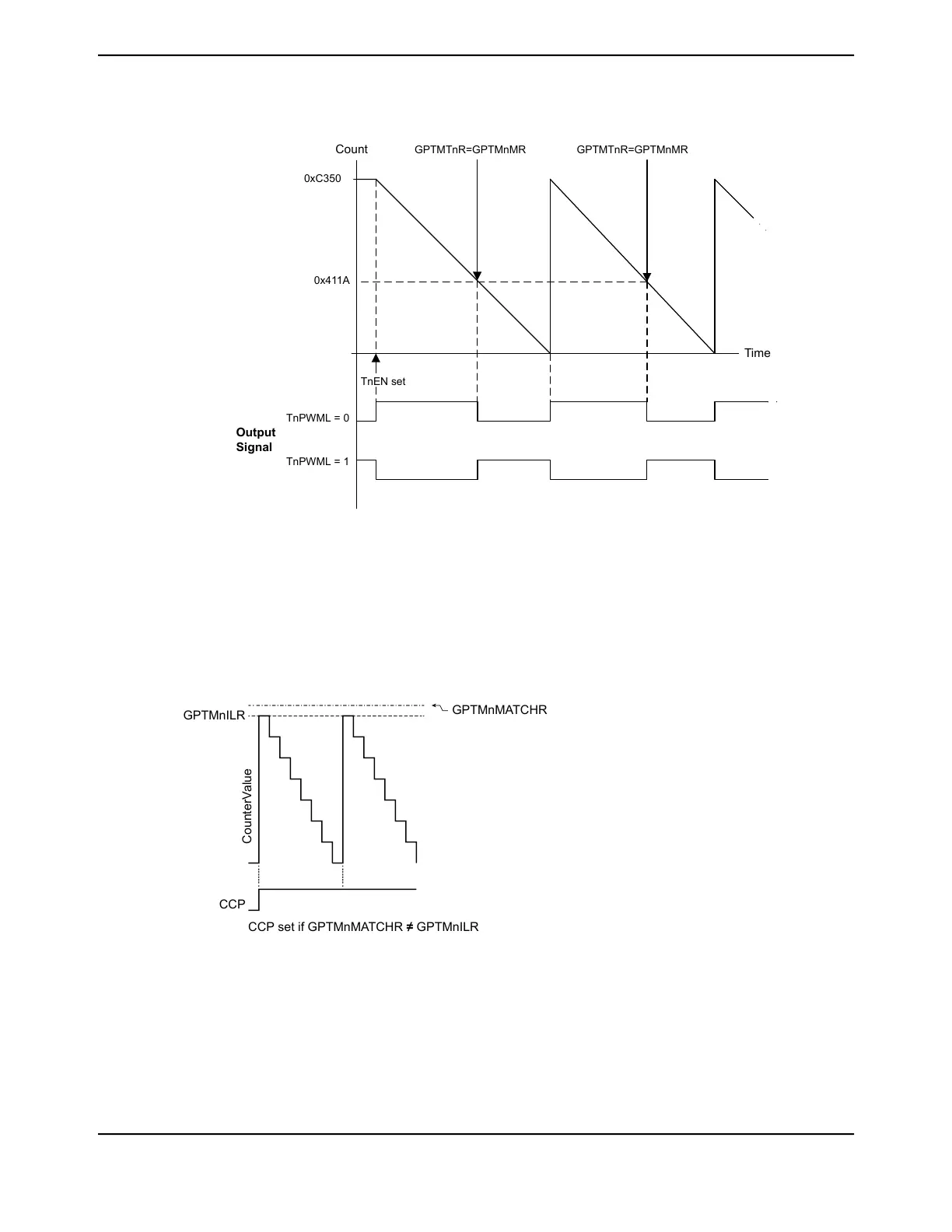
Figure 13-4. 16-Bit PWM Mode Example
Output
Signal
Time
Count
GPTMTnR=GPTMnMR GPTMTnR=GPTMnMR
0xC350
0x411A
TnPWML = 0
TnPWML = 1
TnEN set
When synchronizing the timers using the GPTMSYNC register, the timer must be properly configured
to avoid glitches on the CCP outputs. Both the TnPLO and the TnMRSU bits must be set in the
GPTMTnMR register. Figure 13-5 on page 967 shows how the CCP output operates when the TnPLO
and TnMRSU bits are set and the GPTMTnMATCHR value is greater than the GPTMTnILR value.
Figure 13-5. CCP Output, GPTMTnMATCHR > GPTMTnILR
CCP
CounterValue
GPTMnMATCHR
GPTMnILR
CCP set if GPTMnMATCHR ≠ GPTMnILR
Figure 13-6 on page 968 shows how the CCP output operates when the PLO and MRSU bits are set
and the GPTMTnMATCHR value is the same as the GPTMTnILR value. In this situation, if the PLO
bit is 0, the CCP signal goes high when the GPTMTnILR value is loaded and the match would be
essentially ignored.
967June 18, 2014
Texas Instruments-Production Data
Tiva
™
TM4C1294NCPDT Microcontroller
 Loading...


