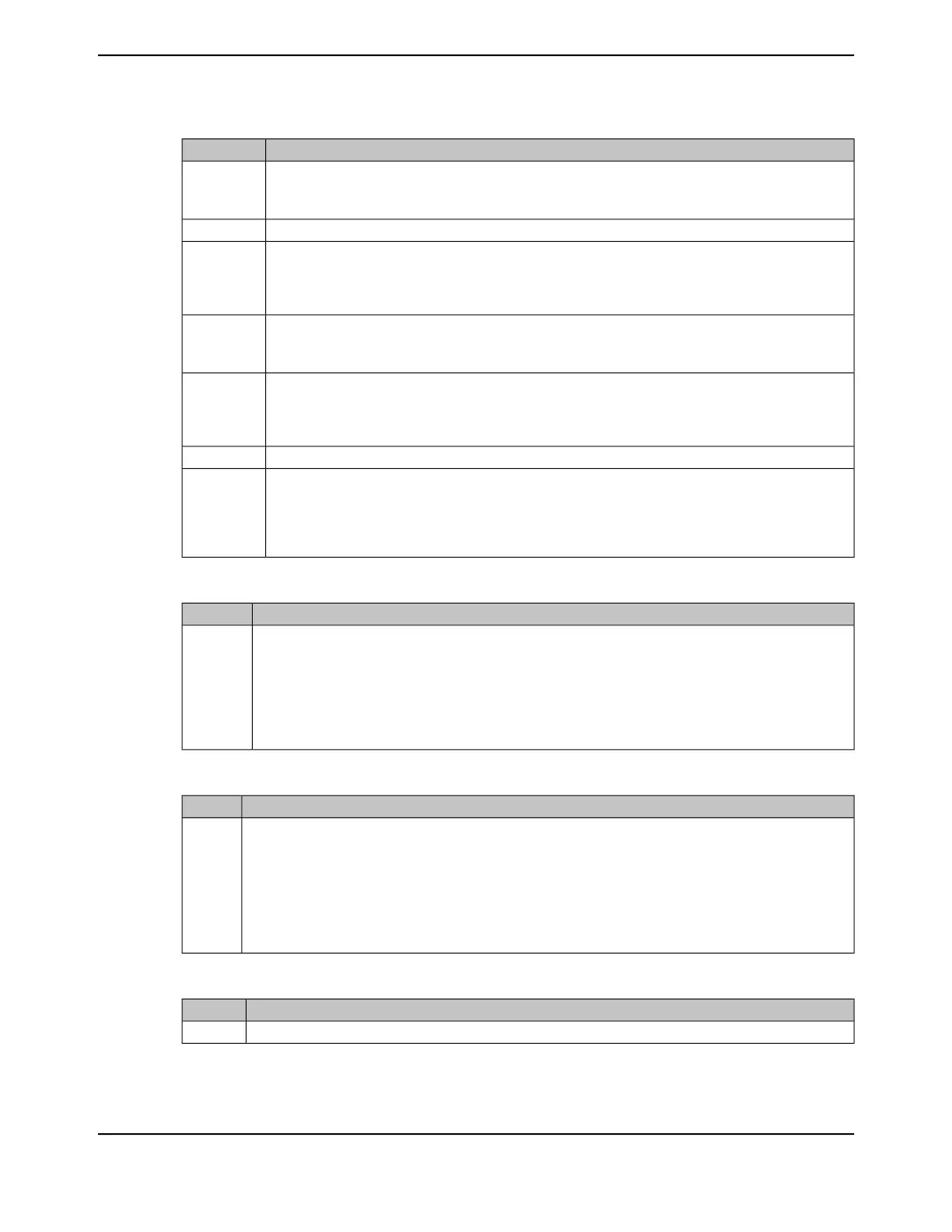
Table 20-10. Enhanced Receive Descriptor 1 (RDES1)
DescriptionBit
Disable Interrupt on Completion
When set, this bit prevents the setting of the Receive Interrupt (RI) bit in the EMACDMARIS register and
prevents the receive interrupt from being asserted.
31
Reserved30:29
RBS2: Receive Buffer 2 Size
These bits indicate the second data buffer size. The buffer size must be a multiple of 4, even if the value of
RDES3 (buffer 2 address pointer) is not aligned to the bus width. When the buffer size is not a multiple of
4, the resulting behavior is undefined. This field is not valid if RCH bit (RDES1[14]) is set.
28:16
RER: Receive End of Ring
When set, this bit indicates that the descriptor list reached its final descriptor. The DMA returns to the base
address of the list, creating a Descriptor Ring.
15
RCH: Second Address Chained
When set, this bit indicates that the second address in the descriptor is the Next Descriptor address rather
than the second buffer address. When this bit is set, RBS2 (RDES1[28:16]) is a "don’t care" value. RDES1[15]
takes precedence over RDES1[14].
14
Reserved13
RBS1: Receive Buffer 1 Size
These bits indicate the first data buffer size in bytes. The buffer size must be a multiple of 4 even if the value
of RDES2 (buffer 1 address pointer) is not aligned to the bus width. When the buffer size is not a multiple
of 4, the resulting behavior is undefined. If this field is 0, the DMA ignores this buffer and uses Buffer 2 or
the next descriptor depending on the value of RCH (Bit 14).
12:0
Table 20-11. Enhanced Receive Descriptor 2 (RDES2)
DescriptionBit
Buffer 1 Address Pointer
These bits indicate the physical address of Buffer 1. The DMA uses the configured value for its address
generation when the RDES2 value is used to store the start of frame. The DMA performs a write operation
with the RDES2[1:0] bits as 0 during the transfer of the start of frame but the frame data is shifted as per the
actual Buffer address pointer. The DMA ignores RDES2[1:0] if the address pointer is to a buffer where the
middle or last part of the frame is stored.
Note that buffers should be word-aligned.
31:0
Table 20-12. Enhanced Receive Descriptor 3 (RDES3)
DescriptionBit
Buffer 2 Address Pointer (Next Descriptor Address)
These bits indicate the physical address of Buffer 2 when a descriptor ring structure is used. If the Second
Address Chained (RDES1[14]) bit is set, this address contains the pointer to the physical memory where the
Next Descriptor is present. If RDES1[14] is set, the buffer (Next Descriptor) address pointer must be bus
word-aligned (RDES3[1:0] = 0) However, when RDES1[14] is reset, there are no limitations on the RDES3 value,
except for the following condition: The DMA uses the configured value for its buffer address generation when
the RDES3 value is used to store the start of frame. The DMA ignores RDES3 [1:0] if the address pointer is to
a buffer where the middle or last part of the frame is stored.
31:0
Table 20-13. Enhanced Received Descriptor 4 (RDES4)
DescriptionBit
Reserved31:15
June 18, 20141422
Texas Instruments-Production Data
Ethernet Controller
 Loading...


