If the system contains a memory map switching mechanism, use a DSB instruction after switching
the memory map in the program. The DSB instruction ensures subsequent instruction execution
uses the updated memory map.
■ Dynamic exception priority change
When an exception priority has to change when the exception is pending or active, use DSB
instructions after the change. The change then takes effect on completion of the DSB instruction.
Memory accesses to Strongly Ordered memory, such as the System Control Block, do not require
the use of DMB instructions.
For more information on the memory barrier instructions, see the Cortex™-M4 instruction set chapter
in the ARM® Cortex™-M4 Devices Generic User Guide (literature number ARM DUI 0553A).
2.4.5 Bit-Banding
A bit-band region maps each word in a bit-band alias region to a single bit in the bit-band region.
The bit-band regions occupy the lowest 1 MB of the SRAM and peripheral memory regions. Accesses
to the 32-MB SRAM alias region map to the 1-MB SRAM bit-band region, as shown in Table
2-6 on page 109. Accesses to the 32-MB peripheral alias region map to the 1-MB peripheral bit-band
region, as shown in Table 2-7 on page 109. For the specific address range of the bit-band regions,
see Table 2-4 on page 103.
Note: A word access to the SRAM or the peripheral bit-band alias region maps to a single bit in
the SRAM or peripheral bit-band region.
A word access to a bit band address results in a word access to the underlying memory,
and similarly for halfword and byte accesses. This allows bit band accesses to match the
access requirements of the underlying peripheral.
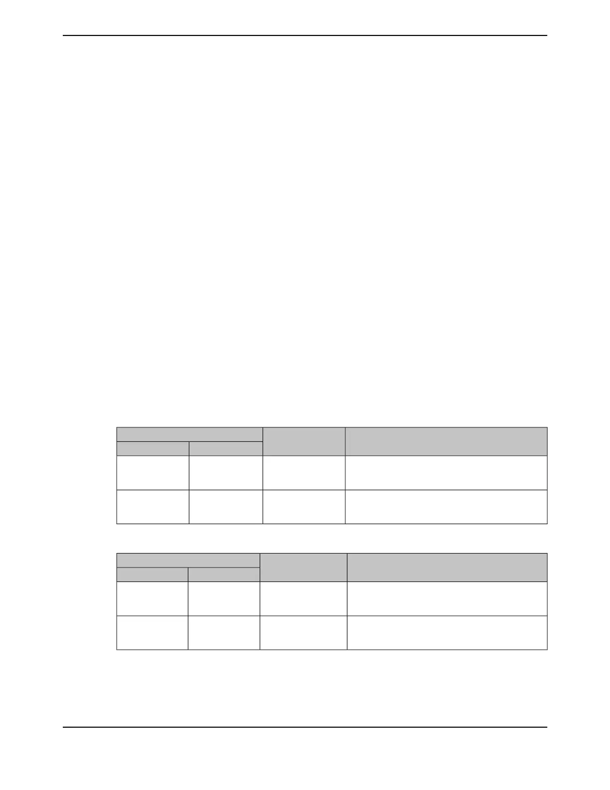
Table 2-6. SRAM Memory Bit-Banding Regions
Instruction and Data AccessesMemory Region
Address Range
EndStart
Direct accesses to this memory range behave as SRAM
memory accesses, but this region is also bit addressable
through bit-band alias.
SRAM bit-band region0x2006.FFFF0x2000.0000
Data accesses to this region are remapped to bit band
region. A write operation is performed as
read-modify-write. Instruction accesses are not remapped.
SRAM bit-band alias0x2234.FFFF0x2200.0000
Table 2-7. Peripheral Memory Bit-Banding Regions
Instruction and Data AccessesMemory Region
Address Range
EndStart
Direct accesses to this memory range behave as
peripheral memory accesses, but this region is also bit
addressable through bit-band alias.
Peripheral bit-band
region
0x400F.FFFF0x4000.0000
Data accesses to this region are remapped to bit band
region. A write operation is performed as
read-modify-write. Instruction accesses are not permitted.
Peripheral bit-band alias0x43FF.FFFF0x4200.0000
The following formula shows how the alias region maps onto the bit-band region:
bit_word_offset = (byte_offset x 32) + (bit_number x 4)
109June 18, 2014
Texas Instruments-Production Data
Tiva
™
TM4C1294NCPDT Microcontroller
 Loading...


