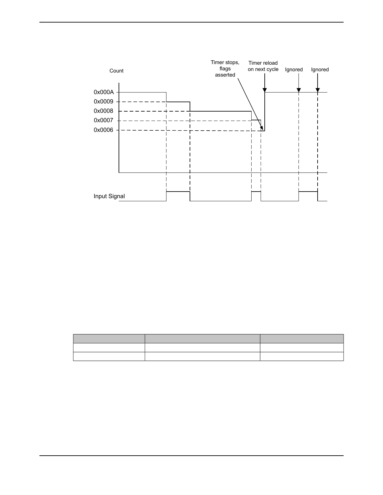
Figure 13-2. Input Edge-Count Mode Example, Counting Down
Input Signal
Timer stops,
flags
asserted
Timer reload
on next cycle
Ignored Ignored
Count
0x000A
0x0006
0x0007
0x0008
0x0009
13.3.3.4 Input Edge-Time Mode
Note: For rising-edge detection, the input signal must be High for at least two system clock periods
following the rising edge. Similarly, for falling edge detection, the input signal must be Low
for at least two system clock periods following the falling edge. Based on this criteria, the
maximum input frequency for edge detection is 1/4 of the system frequency.
In Edge-Time mode, the timer is configured as a 24-bit up- or down-counter including the optional
prescaler with the upper timer value stored in the GPTMTnPR register and the lower bits in the
GPTMTnILR register. In this mode, the timer is initialized to the value loaded in the GPTMTnILR
and GPTMTnPR registers when counting down and 0x0 when counting up. The timer is capable of
capturing three types of events: rising edge, falling edge, or both. The timer is placed into Edge-Time
mode by setting the TnCMR bit in the GPTMTnMR register, and the type of event that the timer
captures is determined by the TnEVENT fields of the GPTMCTL register. Table 13-8 on page 964
shows the values that are loaded into the timer registers when the timer is enabled.
Table 13-8. Counter Values When the Timer is Enabled in Input Event-Count Mode
Count Up ModeCount Down ModeRegister
0x0GPTMTnILRTnR
0x0GPTMTnILRTnV
When software writes the TnEN bit in the GPTMCTL register, the timer is enabled for event capture.
When the selected input event is detected, the current timer counter value is captured in the
GPTMTnR and GPTMTnPS register and is available to be read by the microcontroller. The GPTM
then asserts the CnERIS bit in the GPTM Raw Interrupt Status (GPTMRIS) register, and holds it
until it is cleared by writing the GPTM Interrupt Clear (GPTMICR) register. If the capture mode
event interrupt is enabled in the GPTM Interrupt Mask (GPTMIMR) register, the GPTM also sets
the CnEMIS bit in the GPTM Masked Interrupt Status (GPTMMIS) register. In this mode, the
GPTMTnR and GPTMTnPS registers hold the time at which the selected input event occurred while
June 18, 2014964
Texas Instruments-Production Data
General-Purpose Timers
 Loading...


