tTSeg1 = tProp + tPhase1
tTSeg1 = (1 * t
q
) + (4 * t
q
)
tTSeg1 = 5 * t
q
tTSeg2 = tPhase2
tTSeg2 = (Information Processing Time + 4) × t
q
tTSeg2 = 4 * t
q
\\Assumes IPT=0
tSJW = 4 * t
q
\\Least of 4, Phase1, and Phase2
= TSeg2 -1
= 4-1
= 3
TSEG2
= TSeg1 -1
= 5-1
= 4
TSEG1
= SJW -1
= 4-1
= 3
SJW
= Baud rate prescaler - 1
= 50-1
=49
BRP
The final value programmed into the CANBIT register = 0x34F1.
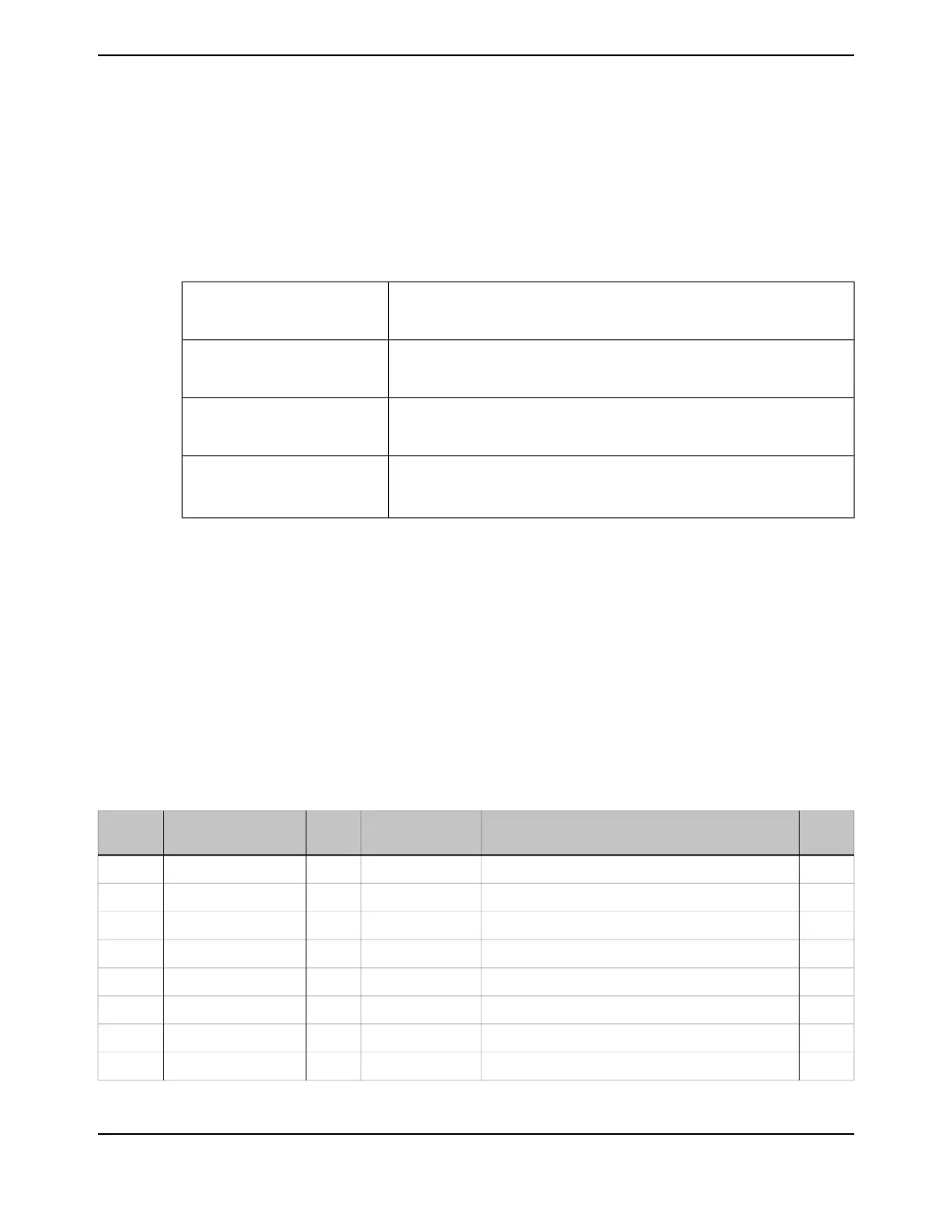
19.4 Register Map
Table 19-5 on page 1375 lists the registers. All addresses given are relative to the CAN base address
of:
■ CAN0: 0x4004.0000
■ CAN1: 0x4004.1000
Note that the CAN controller clock must be enabled before the registers can be programmed (see
page 395). There must be a delay of 3 system clocks after the CAN module clock is enabled before
any CAN module registers are accessed.
Table 19-5. CAN Register Map
See
page
DescriptionResetTypeNameOffset
1378CAN Control0x0000.0001RWCANCTL0x000
1380CAN Status0x0000.0000RWCANSTS0x004
1383CAN Error Counter0x0000.0000ROCANERR0x008
1384CAN Bit Timing0x0000.2301RWCANBIT0x00C
1385CAN Interrupt0x0000.0000ROCANINT0x010
1386CAN Test0x0000.0000RWCANTST0x014
1388CAN Baud Rate Prescaler Extension0x0000.0000RWCANBRPE0x018
1389CAN IF1 Command Request0x0000.0001RWCANIF1CRQ0x020
1375June 18, 2014
Texas Instruments-Production Data
Tiva
™
TM4C1294NCPDT Microcontroller
 Loading...


