In the case of a single word transfer, after all bits have been transferred, the SSInFss line is returned
to its idle High state one SSInClk period after the last bit has been captured.
For continuous back-to-back transfers, the SSInFss pin is held Low between successive data
words, and termination is the same as that of the single word transfer.
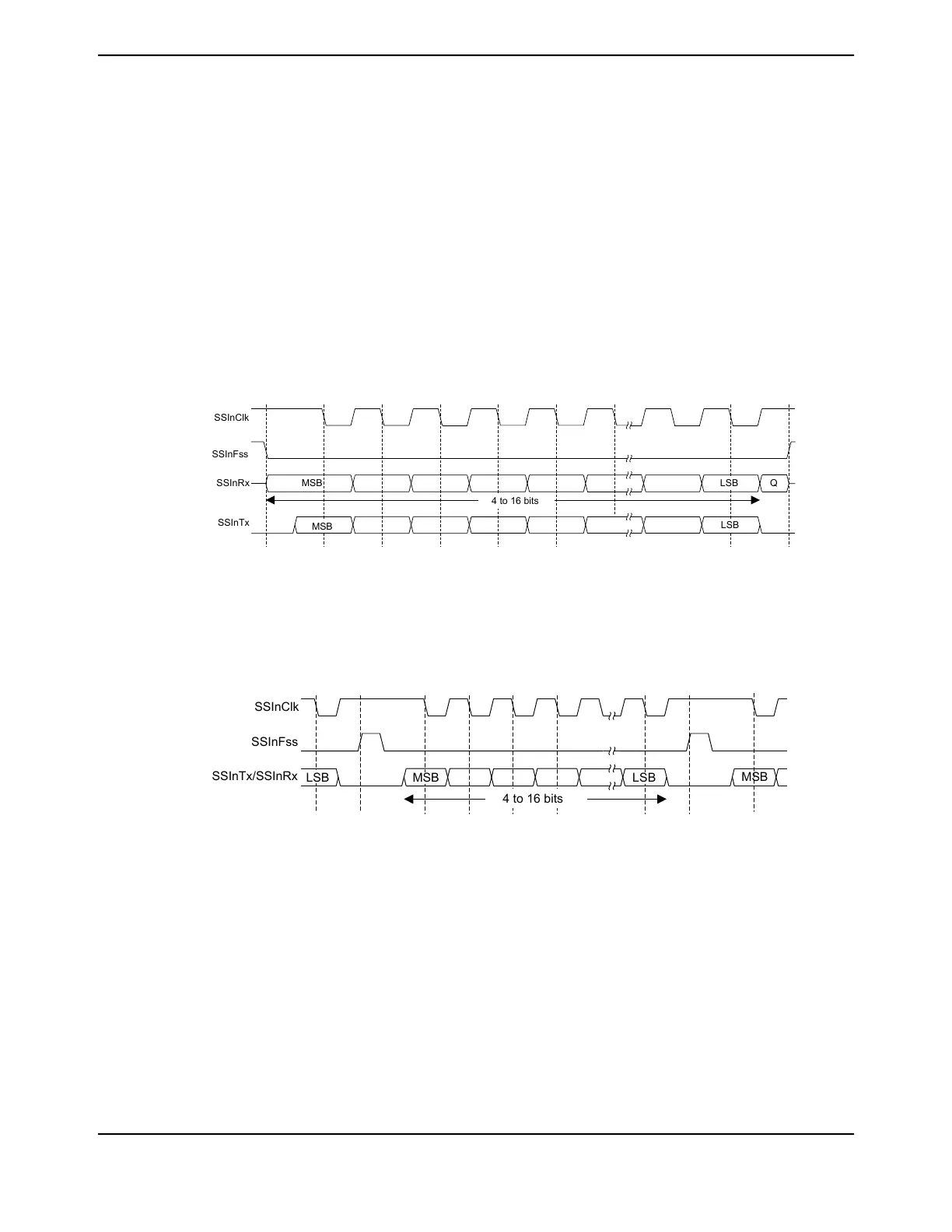
17.3.7.5 Freescale SPI Frame Format with SPO=1 and SPH=0
Single and continuous transmission signal sequences for Freescale SPI format with SPO=1 and
SPH=0 are shown in Figure 17-7 on page 1238 and Figure 17-8 on page 1238.
Note: This Freescale SPI frame format configuration is only available when operating in Legacy
SSI mode of operation.
Figure 17-7. Freescale SPI Frame Format (Single Transfer) with SPO=1 and SPH=0
SSInClk
SSInFss
SSInRx
SSInTx
QMSB
MSB
LSB
LSB
4 to 16 bits
Note: Q is undefined.
Figure 17-8. Freescale SPI Frame Format (Continuous Transfer) with SPO=1 and SPH=0
SSInClk
SSInFss
SSInTx/SSInRx
MSB LSB
LSB
MSB
4 to 16 bits
In this configuration, during idle periods:
■ SSInClk is forced High
■ SSInFss is forced High
■ The transmit data line SSInDAT0/SSInTX is tristated
■ When the QSSI is configured as a master, it enables the SSInClk pad
■ When the QSSI is configured as a slave, it disables the SSInClk pad
June 18, 20141238
Texas Instruments-Production Data
Quad Synchronous Serial Interface (QSSI)
 Loading...


