18.3.6.2 I
2
C Slave Command Sequences
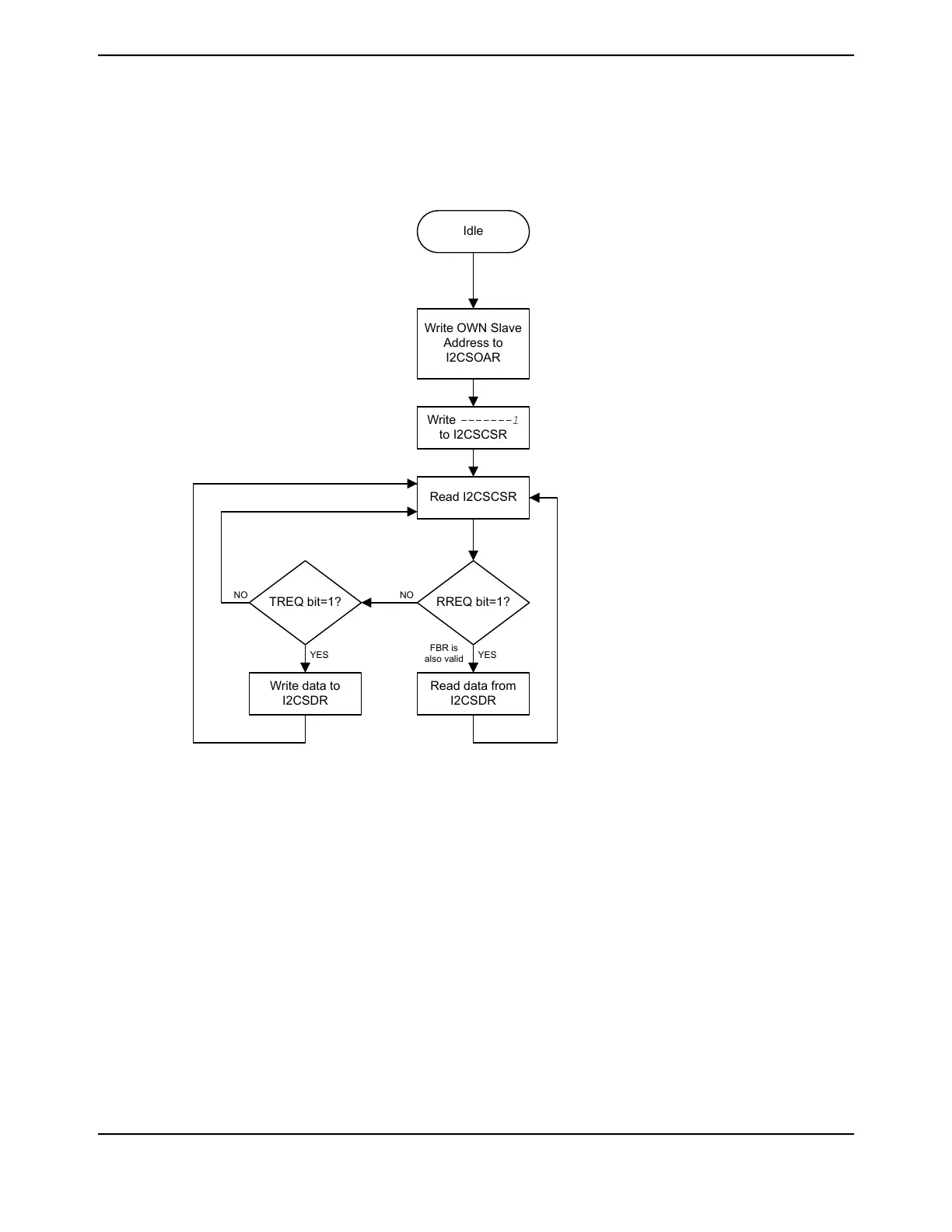
Figure 18-15 on page 1297 presents the command sequence available for the I
2
C slave.
Figure 18-15. Slave Command Sequence
Idle
Write OWN Slave
Address to
I2CSOAR
Write -------1
to I2CSCSR
Read I2CSCSR
RREQ bit=1?
Read data from
I2CSDR
YES
TREQ bit=1?
NO
Write data to
I2CSDR
YES
NO
FBR is
also valid
18.4 Initialization and Configuration
18.4.1 Configure the I
2
C Module to Transmit a Single Byte as a Master
The following example shows how to configure the I
2
C module to transmit a single byte as a master.
This assumes the system clock is 20 MHz.
1. Enable the I
2
C clock using the RCGCI2C register in the System Control module (see page 391).
2. Enable the clock to the appropriate GPIO module via the RCGCGPIO register in the System
Control module (see page 382). To find out which GPIO port to enable, refer to Table
26-5 on page 1808.
3. In the GPIO module, enable the appropriate pins for their alternate function using the
GPIOAFSEL register (see page 770). To determine which GPIOs to configure, see Table
26-4 on page 1797.
1297June 18, 2014
Texas Instruments-Production Data
Tiva
™
TM4C1294NCPDT Microcontroller
 Loading...


