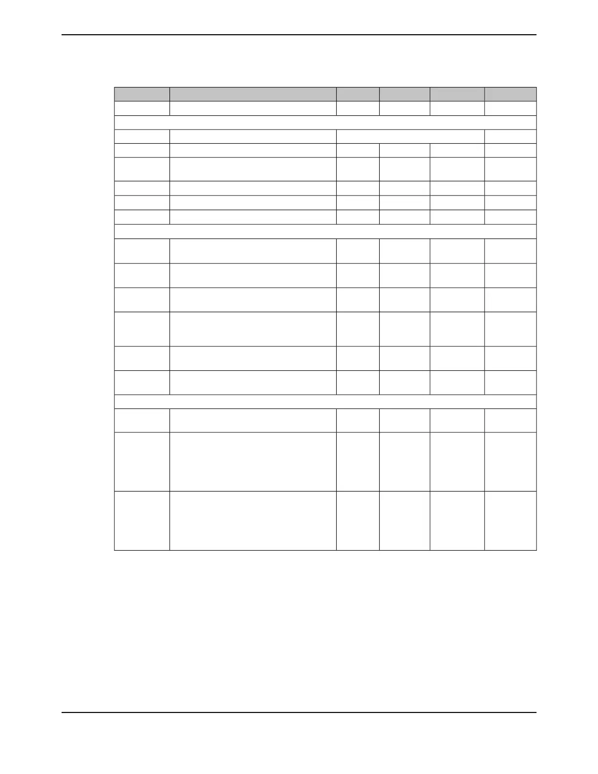
Table 27-44. ADC Electrical Characteristics for ADC at 1 Msps (continued)
UnitMaxNomMinParameter NameParameter
LSB±4.0±2.5-Total unadjusted error, over full input range
p
E
T
SYSTEM PERFORMANCE when using internal reference
bits12ResolutionN
LSB±3.0±1.5-Integral nonlinearity error, over full input rangeINL
LSB+2.0/-1.0
n
±0.8-Differential nonlinearity error, over full input
range
DNL
LSB±15.0±5.0-Offset errorE
O
LSB±30.0±10.0-Gain error
o
E
G
LSB±30.0±10.0-Total unadjusted error, over full input range
p
E
T
DYNAMIC CHARACTERISTICS
qr
dB-7270Signal-to-noise-ratio, Differential input, V
ADCIN
:
-20dB FS, 1KHz
s
SNR
D
dB-7572Signal-to-distortion ratio, Differential input,
V
ADCIN
: -3dB FS, 1KHz
stu
SDR
D
dB-7068Signal-to-Noise+Distortion ratio, Differential
input, V
ADCIN
: -3dB FS, 1KHz
svw
SNDR
D
dB-6560Signal-to-noise-ratio, Single-ended input, V
ADCIN
:
-20dB FS, 1KHz
x
SNR
S
dB-7270Signal-to-distortion ratio, Single-ended input,
V
ADCIN
: -3dB FS, 1KHz
tu
SDR
S
dB-6360Signal-to-Noise+Distortion ratio, Single-ended
input, V
ADCIN
: -3dB FS, 1KHz
xvw
SNDR
S
TEMPERATURE SENSOR
V-1.633-Temperature sensor voltage, junction
temperature 25 °C
V
TSENS
mV/°C--13.3-Temperature sensor slope at:
-40°C to 85 °C ambient (industrial temperature
part)
-40°C to 105 °C ambient (extended temperature
part)
S
TSENS
°C±5--Temperature sensor accuracy at:
y
-40°C to 85 °C ambient (industrial temperature
part)
-40°C to 105 °C ambient (extended temperature
part)
E
TSENS
a. Values are at V
REF+
= 3.3V, F
ADC
=16 MHz unless otherwise noted.
b. Best design practices suggest that static or quiet digital I/O signals be configured adjacent to sensitive analog inputs to
reduce capacitive coupling and cross talk. Unexpected results can occur if a switching digital I/O is placed adjacent to
an ADC input channel or voltage reference input. In addition, analog signals configured adjacent to ADC input channels
or reference inputs must meet the R
ADC
equivalent input resistance given in this table and must be band-limited to 100
kHz or lower.
c. Two capacitors in parallel. Note that these capacitors should be as close to the die as possible.
d. Internal reference is connected directly between V
DDA
and GNDA (VREFi = V
DDA
- GNDA). In this mode, E
O
, E
G
, E
T
, and
dynamic specifications are adversely affected due to internal voltage drop and noise on V
DDA
and GNDA. Internal
reference voltage is selected when VREF field in the ADCCTL register is 0x0.
e. V
ADCIN
= V
INP
- V
INN
f. With signal common mode as V
DDA
/2.
June 18, 20141862
Texas Instruments-Production Data
Electrical Characteristics
 Loading...


