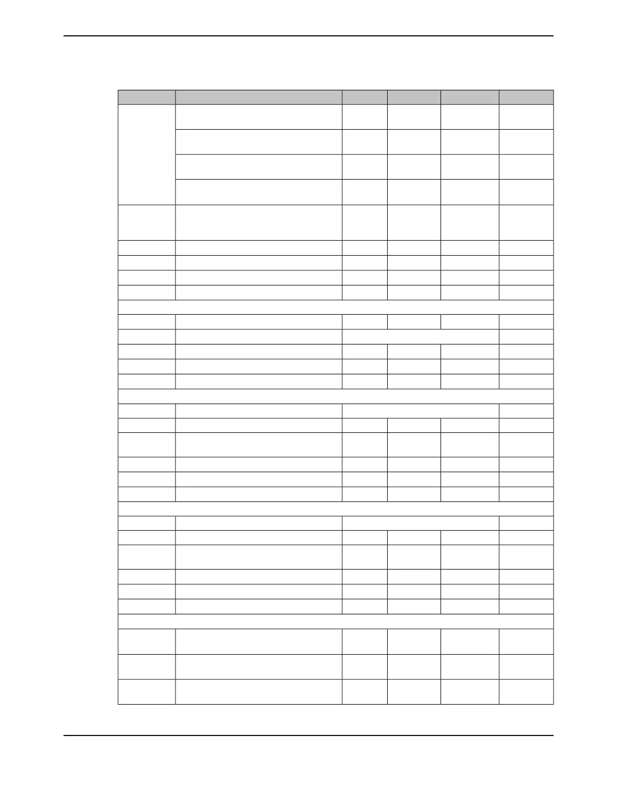
Table 27-45. ADC Electrical Characteristics for ADC at 2 Msps (continued)
UnitMaxNomMinParameter NameParameter
VV
DDA
-0Single-ended, full- scale analog input voltage,
internal reference
ef
V
ADCIN
VV
VDDA
--V
DDA
Differential, full-scale analog input voltage,
internal reference
eg
VV
REFA+
-V
REFA-
Single-ended, full-scale analog input voltage,
external reference
df
VV
REFA+
- V
REFA-
-- (V
REFA+
-
V
REFA-
)
Differential, full-scale analog input voltage,
external reference
dh
V[(V
REFA+
+
V
REFA-
) / 2] ±
0.025
--Input common mode voltage, differential mode
i
VIN
CM
µA2.0--ADC input leakage current
j
I
L
kΩ2.5--ADC equivalent input resistance
j
R
ADC
pF10--ADC equivalent input capacitance
j
C
ADC
Ω250--Analog source resistance
j
R
S
SAMPLING DYNAMICS
MHz-32-ADC conversion clock frequency
k
F
ADC
Msps2ADC conversion rateF
CONV
ns-125-ADC sample timeT
S
µs-0.5-ADC conversion time
l
T
C
ADC clocks-2-Latency from trigger to start of conversionT
LT
SYSTEM PERFORMANCE when using external reference
mn
bits12ResolutionN
LSB±3.0±1.5-Integral nonlinearity error, over full input rangeINL
LSB+2.0/-1.0
o
±0.8-Differential nonlinearity error, over full input
range
DNL
LSB±3.0±1.0-Offset errorE
O
LSB±3.0±2.0-Gain error
p
E
G
LSB±4.0±2.5-Total unadjusted error, over full input range
q
E
T
SYSTEM PERFORMANCE when using internal reference
bits12ResolutionN
LSB±3.0±1.5-Integral nonlinearity error, over full input rangeINL
LSB+2.0/-1.0
o
±0.8-Differential nonlinearity error, over full input
range
DNL
LSB±15.0±5.0-Offset errorE
O
LSB±30.0±10.0-Gain error
p
E
G
LSB±30.0±10.0-Total unadjusted error, over full input range
q
E
T
DYNAMIC CHARACTERISTICS
rs
dB-7268Signal-to-noise-ratio, Differential input, V
ADCIN
:
-20dB FS, 1KHz
t
SNR
D
dB-7570Signal-to-distortion ratio, Differential input,
V
ADCIN
: -3dB FS, 1KHz
tuv
SDR
D
dB-7065Signal-to-Noise+Distortion ratio, Differential
input, V
ADCIN
: -3dB FS, 1KHz
twx
SNDR
D
June 18, 20141864
Texas Instruments-Production Data
Electrical Characteristics

 Loading...


