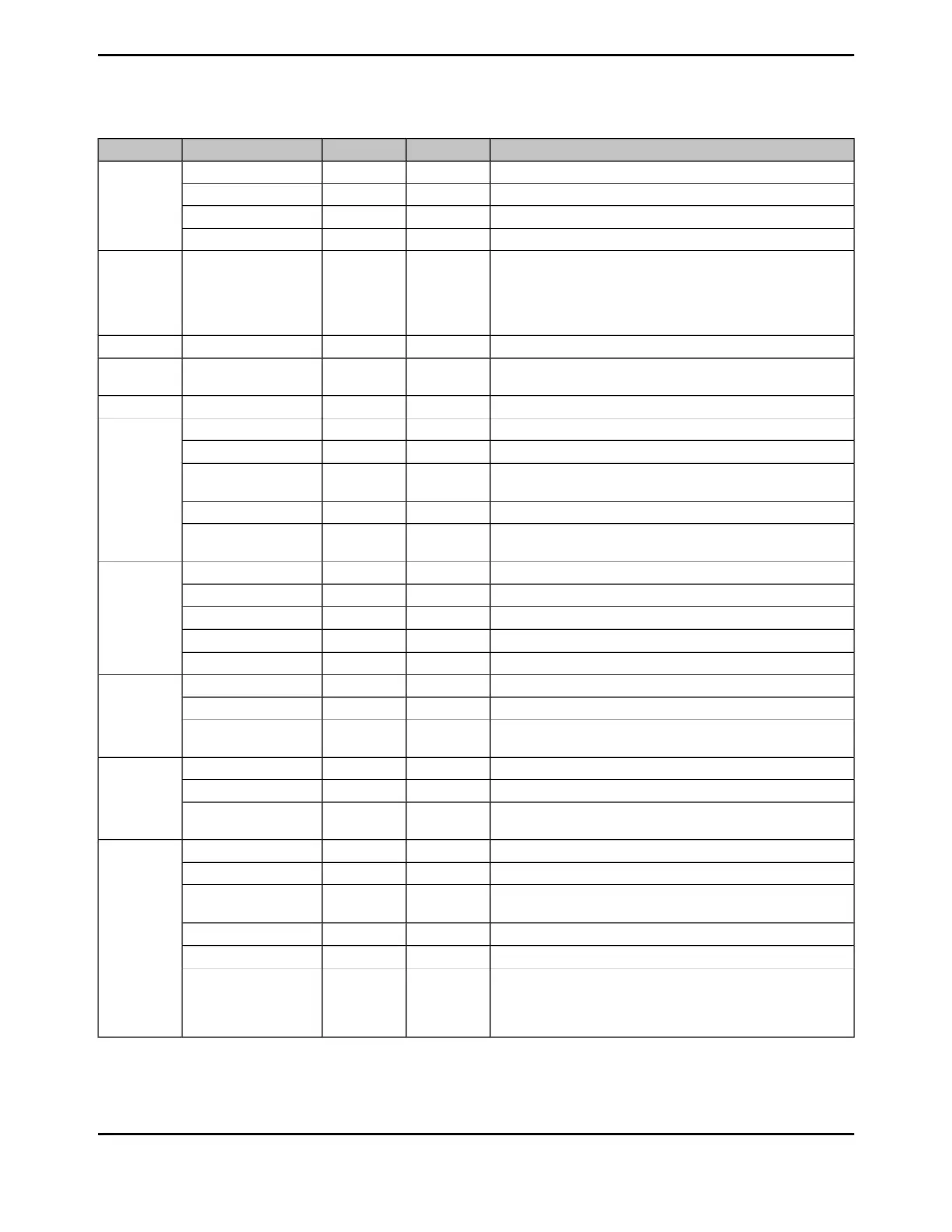
Table 26-2. Signals by Pin Number (continued)
DescriptionBuffer TypePin TypePin NamePin Number
GPIO port L bit 5.TTLI/OPL5
86
EPI module 0 signal 33.TTLI/OEPI0S33
16/32-Bit Timer 0 Capture/Compare/PWM 1.TTLI/OT0CCP1
USB data 5.TTLI/OUSB0D5
Positive supply for most of the logic function, including the
processor core and most peripherals. The voltage on this pin is
1.2 V and is supplied by the on-chip LDO. The VDDC pins should
only be connected to each other and an external capacitor as
specified in Table 27-15 on page 1834 .
Power-VDDC
87
Main oscillator crystal input or an external clock reference input.AnalogIOSC0
88
Main oscillator crystal output. Leave unconnected when using a
single-ended clock source.
AnalogOOSC1
89
Positive supply for I/O and some logic.Power-VDD
90
GPIO port B bit 2.TTLI/OPB2
91
EPI module 0 signal 27.TTLI/OEPI0S27
I
2
C module 0 clock. Note that this signal has an active pull-up. The
corresponding port pin should not be configured as open drain.
ODI/OI2C0SCL
16/32-Bit Timer 5 Capture/Compare/PWM 0.TTLI/OT5CCP0
Asserted by the USB controller to signal the end of a USB transmit
packet or register write operation.
TTLOUSB0STP
GPIO port B bit 3.TTLI/OPB3
92
EPI module 0 signal 28.TTLI/OEPI0S28
I
2
C module 0 data.ODI/OI2C0SDA
16/32-Bit Timer 5 Capture/Compare/PWM 1.TTLI/OT5CCP1
60-MHz clock to the external PHY.TTLOUSB0CLK
GPIO port L bit 7.TTLI/OPL7
93
16/32-Bit Timer 1 Capture/Compare/PWM 1.TTLI/OT1CCP1
Bidirectional differential data pin (D- per USB specification) for
USB0.
AnalogI/OUSB0DM
GPIO port L bit 6.TTLI/OPL6
94
16/32-Bit Timer 1 Capture/Compare/PWM 0.TTLI/OT1CCP0
Bidirectional differential data pin (D+ per USB specification) for
USB0.
AnalogI/OUSB0DP
GPIO port B bit 0.TTLI/OPB0
95
CAN module 1 receive.TTLICAN1Rx
I
2
C module 5 clock. Note that this signal has an active pull-up. The
corresponding port pin should not be configured as open drain.
ODI/OI2C5SCL
16/32-Bit Timer 4 Capture/Compare/PWM 0.TTLI/OT4CCP0
UART module 1 receive.TTLIU1Rx
This signal senses the state of the USB ID signal. The USB PHY
enables an integrated pull-up, and an external element (USB
connector) indicates the initial state of the USB controller (pulled
down is the A side of the cable and pulled up is the B side).
AnalogIUSB0ID
1781June 18, 2014
Texas Instruments-Production Data
Tiva
™
TM4C1294NCPDT Microcontroller
 Loading...


