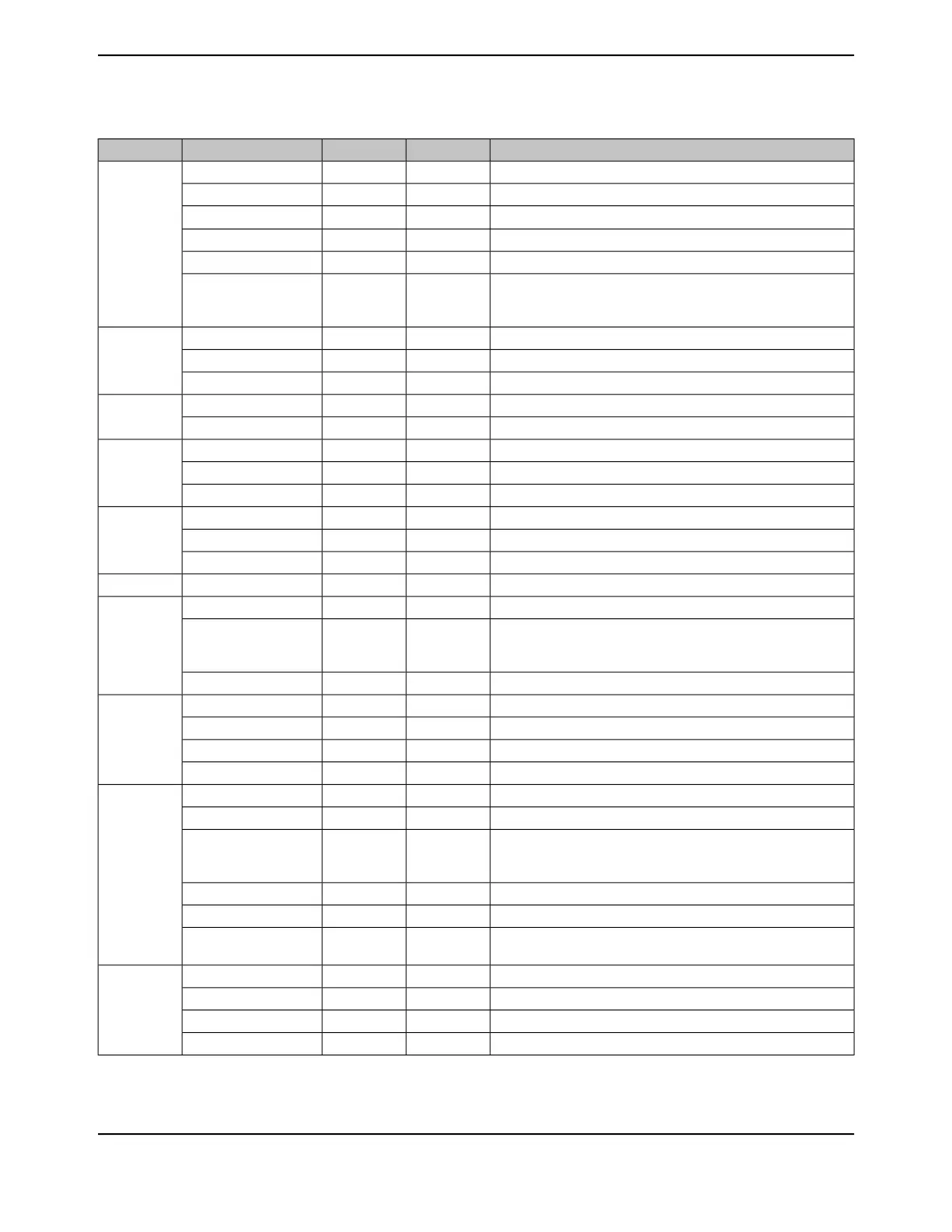
Table 26-2. Signals by Pin Number (continued)
DescriptionBuffer TypePin TypePin NamePin Number
GPIO port B bit 1.TTLI/OPB1
96
CAN module 1 transmit.TTLOCAN1Tx
I
2
C module 5 data.ODI/OI2C5SDA
16/32-Bit Timer 4 Capture/Compare/PWM 1.TTLI/OT4CCP1
UART module 1 transmit.TTLOU1Tx
This signal is used during the session request protocol. This signal
allows the USB PHY to both sense the voltage level of VBUS, and
pull up VBUS momentarily during VBUS pulsing.
AnalogI/OUSB0VBUS
GPIO port C bit 3.TTLI/OPC3
97
JTAG TDO and SWO.TTLOSWO
JTAG TDO and SWO.TTLOTDO
GPIO port C bit 2.TTLI/OPC2
98
JTAG TDI.TTLITDI
GPIO port C bit 1.TTLI/OPC1
99
JTAG TMS and SWDIO.TTLI/OSWDIO
JTAG TMS and SWDIO.TTLITMS
GPIO port C bit 0.TTLI/OPC0
100
JTAG/SWD CLK.TTLISWCLK
JTAG/SWD CLK.TTLITCK
Positive supply for I/O and some logic.Power-VDD
101
GPIO port Q bit 4.TTLI/OPQ4
102
An optionally divided reference clock output based on a selected
clock source. Note that this signal is not synchronized to the System
Clock.
TTLODIVSCLK
UART module 1 receive.TTLIU1Rx
GPIO port P bit 2.TTLI/OPP2
103
EPI module 0 signal 29.TTLI/OEPI0S29
UART module 0 Data Terminal Ready modem status input signal.TTLOU0DTR
Asserted by the external PHY to throttle all data types.TTLOUSB0NXT
GPIO port P bit 3.TTLI/OPP3
104
EPI module 0 signal 30.TTLI/OEPI0S30
Buffered version of the Hibernation module's 32.768-kHz clock.
This signal is not output when the part is in Hibernate mode and
before being configured after power-on reset.
TTLORTCCLK
UART module 0 Data Carrier Detect modem status input signal.TTLIU0DCD
UART module 1 Clear To Send modem flow control input signal.TTLIU1CTS
Indicates that the external PHY is able to accept data from the USB
controller.
TTLOUSB0DIR
GPIO port P bit 4.TTLI/OPP4
105
UART module 0 Data Set Ready modem output control line.TTLIU0DSR
UART module 3 Request to Send modem flow control output line.TTLOU3RTS
USB data 7.TTLI/OUSB0D7
June 18, 20141782
Texas Instruments-Production Data
Signal Tables
 Loading...


