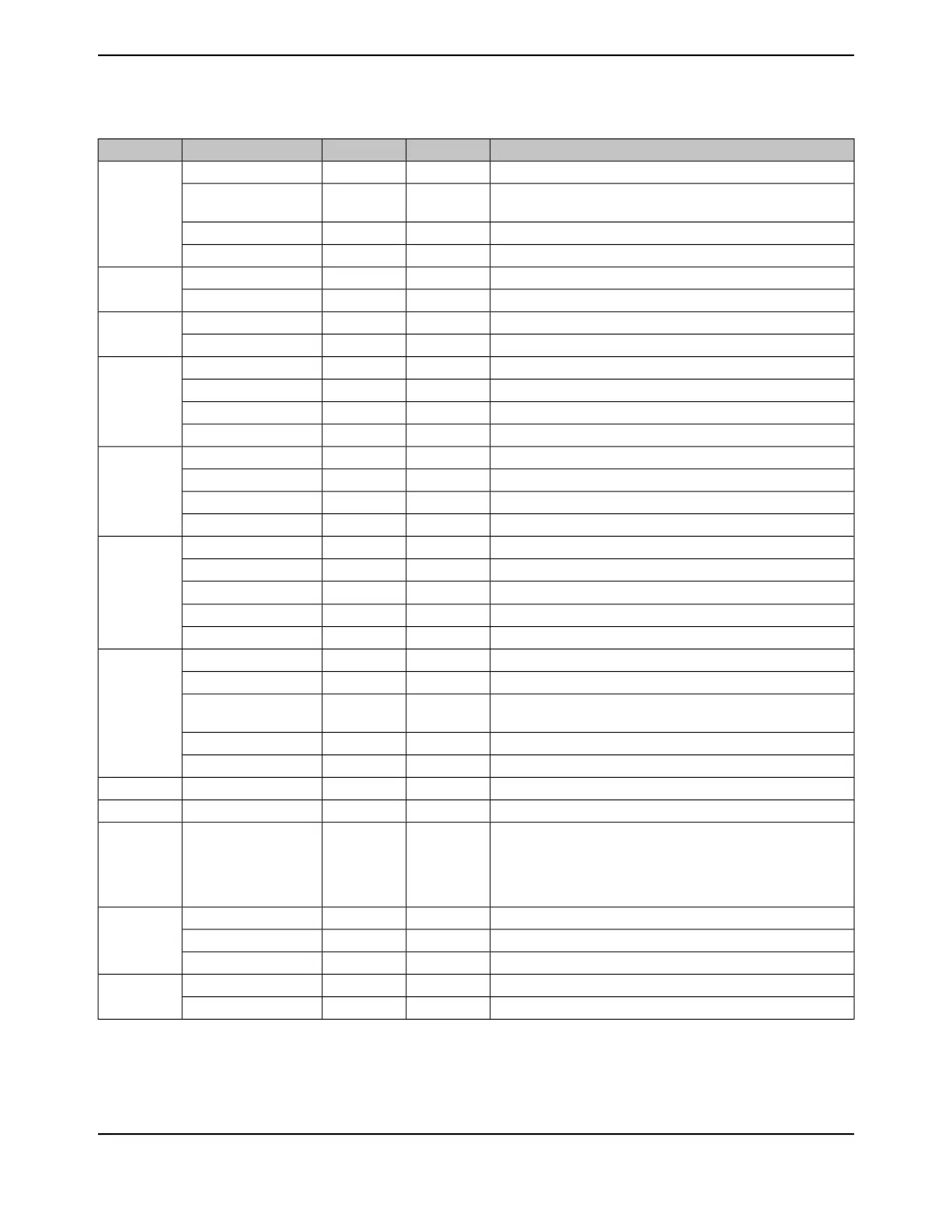
Table 26-2. Signals by Pin Number (continued)
DescriptionBuffer TypePin TypePin NamePin Number
GPIO port P bit 5.TTLI/OPP5
106
I
2
C module 2 clock. Note that this signal has an active pull-up. The
corresponding port pin should not be configured as open drain.
ODI/OI2C2SCL
UART module 3 Clear To Send modem flow control input signal.TTLIU3CTS
USB data 6.TTLI/OUSB0D6
GPIO port N bit 0.TTLI/OPN0
107
UART module 1 Request to Send modem flow control output line.TTLOU1RTS
GPIO port N bit 1.TTLI/OPN1
108
UART module 1 Clear To Send modem flow control input signal.TTLIU1CTS
GPIO port N bit 2.TTLI/OPN2
109
EPI module 0 signal 29.TTLI/OEPI0S29
UART module 1 Data Carrier Detect modem status input signal.TTLIU1DCD
UART module 2 Request to Send modem flow control output line.TTLOU2RTS
GPIO port N bit 3.TTLI/OPN3
110
EPI module 0 signal 30.TTLI/OEPI0S30
UART module 1 Data Set Ready modem output control line.TTLIU1DSR
UART module 2 Clear To Send modem flow control input signal.TTLIU2CTS
GPIO port N bit 4.TTLI/OPN4
111
EPI module 0 signal 34.TTLI/OEPI0S34
I
2
C module 2 data.ODI/OI2C2SDA
UART module 1 Data Terminal Ready modem status input signal.TTLOU1DTR
UART module 3 Request to Send modem flow control output line.TTLOU3RTS
GPIO port N bit 5.TTLI/OPN5
112
EPI module 0 signal 35.TTLI/OEPI0S35
I
2
C module 2 clock. Note that this signal has an active pull-up. The
corresponding port pin should not be configured as open drain.
ODI/OI2C2SCL
UART module 1 Ring Indicator modem status input signal.TTLIU1RI
UART module 3 Clear To Send modem flow control input signal.TTLIU3CTS
Positive supply for I/O and some logic.Power-VDD
113
Ground reference for logic and I/O pins.Power-GND
114
Positive supply for most of the logic function, including the
processor core and most peripherals. The voltage on this pin is
1.2 V and is supplied by the on-chip LDO. The VDDC pins should
only be connected to each other and an external capacitor as
specified in Table 27-15 on page 1834 .
Power-VDDC
115
GPIO port J bit 0.TTLI/OPJ0
116
Ethernet 0 Pulse-Per-Second (PPS) Output.TTLOEN0PPS
UART module 3 receive.TTLIU3Rx
GPIO port J bit 1.TTLI/OPJ1
117
UART module 3 transmit.TTLOU3Tx
1783June 18, 2014
Texas Instruments-Production Data
Tiva
™
TM4C1294NCPDT Microcontroller
 Loading...


