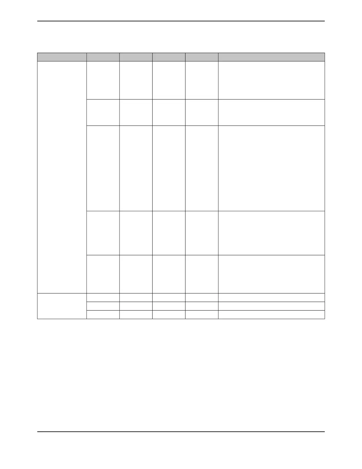
Table 26-4. Signals by Function, Except for GPIO (continued)
DescriptionBuffer TypePin TypePin NumberPin NameFunction
Ground reference for logic and I/O pins.Power-17
48
55
58
80
114
GND
Power
The ground reference for the analog circuits (ADC,
Analog Comparators, etc.). These are separated
from GND to minimize the electrical noise contained
on VDD from affecting the analog functions.
Power-10GNDA
Positive supply for I/O and some logic.Power-7
16
26
28
39
47
51
52
69
79
90
101
113
122
VDD
The positive supply for the analog circuits (ADC,
Analog Comparators, etc.). These are separated
from VDD to minimize the electrical noise contained
on VDD from affecting the analog functions. VDDA
pins must be supplied with a voltage that meets the
specification in , regardless of system
implementation.
Power-8VDDA
Positive supply for most of the logic function,
including the processor core and most peripherals.
The voltage on this pin is 1.2 V and is supplied by
the on-chip LDO. The VDDC pins should only be
connected to each other and an external capacitor
as specified in Table 27-15 on page 1834 .
Power-87
115
VDDC
QEI module 0 index.TTLI84IDX0
QEI
QEI module 0 phase A.TTLI82PhA0
QEI module 0 phase B.TTLI83PhB0
June 18, 20141804
Texas Instruments-Production Data
Signal Tables
 Loading...


