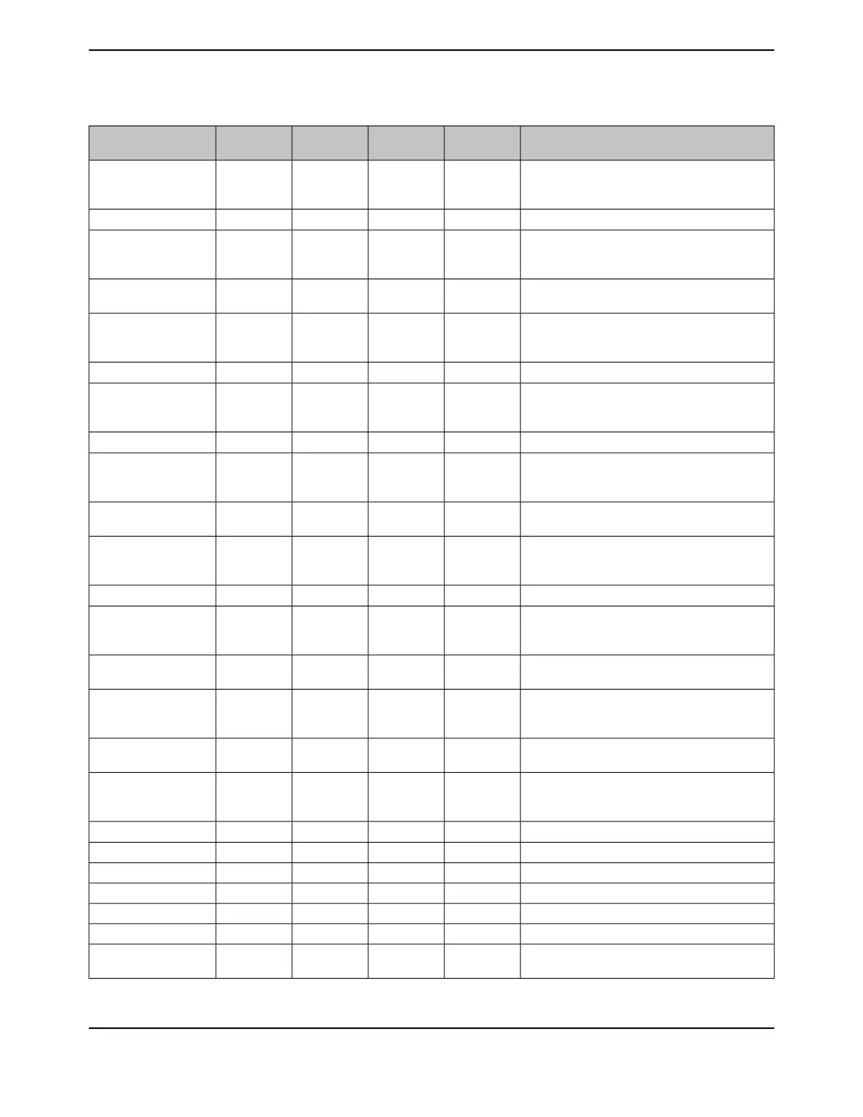
Table 26-3. Signals by Signal Name (continued)
DescriptionBuffer TypePin TypePin Mux / Pin
Assignment
Pin NumberPin Name
I
2
C module 1 clock. Note that this signal has an
active pull-up. The corresponding port pin should
not be configured as open drain.
ODI/OPG0 (2)49I2C1SCL
I
2
C module 1 data.ODI/OPG1 (2)50I2C1SDA
I
2
C module 2 clock. Note that this signal has an
active pull-up. The corresponding port pin should
not be configured as open drain.
ODI/OPL1 (2)
PP5 (2)
PN5 (3)
82
106
112
I2C2SCL
I
2
C module 2 data.ODI/OPL0 (2)
PN4 (3)
81
111
I2C2SDA
I
2
C module 3 clock. Note that this signal has an
active pull-up. The corresponding port pin should
not be configured as open drain.
ODI/OPK4 (2)63I2C3SCL
I
2
C module 3 data.ODI/OPK5 (2)62I2C3SDA
I
2
C module 4 clock. Note that this signal has an
active pull-up. The corresponding port pin should
not be configured as open drain.
ODI/OPK6 (2)61I2C4SCL
I
2
C module 4 data.ODI/OPK7 (2)60I2C4SDA
I
2
C module 5 clock. Note that this signal has an
active pull-up. The corresponding port pin should
not be configured as open drain.
ODI/OPB0 (2)
PB4 (2)
95
121
I2C5SCL
I
2
C module 5 data.ODI/OPB1 (2)
PB5 (2)
96
120
I2C5SDA
I
2
C module 6 clock. Note that this signal has an
active pull-up. The corresponding port pin should
not be configured as open drain.
ODI/OPA6 (2)40I2C6SCL
I
2
C module 6 data.ODI/OPA7 (2)41I2C6SDA
I
2
C module 7 clock. Note that this signal has an
active pull-up. The corresponding port pin should
not be configured as open drain.
ODI/OPD0 (2)
PA4 (2)
1
37
I2C7SCL
I
2
C module 7 data.ODI/OPD1 (2)
PA5 (2)
2
38
I2C7SDA
I
2
C module 8 clock. Note that this signal has an
active pull-up. The corresponding port pin should
not be configured as open drain.
ODI/OPD2 (2)
PA2 (2)
3
35
I2C8SCL
I
2
C module 8 data.ODI/OPD3 (2)
PA3 (2)
4
36
I2C8SDA
I
2
C module 9 clock. Note that this signal has an
active pull-up. The corresponding port pin should
not be configured as open drain.
ODI/OPA0 (2)33I2C9SCL
I
2
C module 9 data.ODI/OPA1 (2)34I2C9SDA
QEI module 0 index.TTLIPL3 (6)84IDX0
Motion Control Module 0 PWM Fault 0.TTLIPF4 (6)46M0FAULT0
Motion Control Module 0 PWM Fault 1.TTLIPK6 (6)61M0FAULT1
Motion Control Module 0 PWM Fault 2.TTLIPK7 (6)60M0FAULT2
Motion Control Module 0 PWM Fault 3.TTLIPL0 (6)81M0FAULT3
Motion Control Module 0 PWM 0. This signal is
controlled by Module 0 PWM Generator 0.
TTLOPF0 (6)42M0PWM0
June 18, 20141788
Texas Instruments-Production Data
Signal Tables
 Loading...


