IO Wrap Register Map
www.ti.com
1002
SBAU337–May 2020
Submit Documentation Feedback
Copyright © 2020, Texas Instruments Incorporated
Serial Interface Register Maps
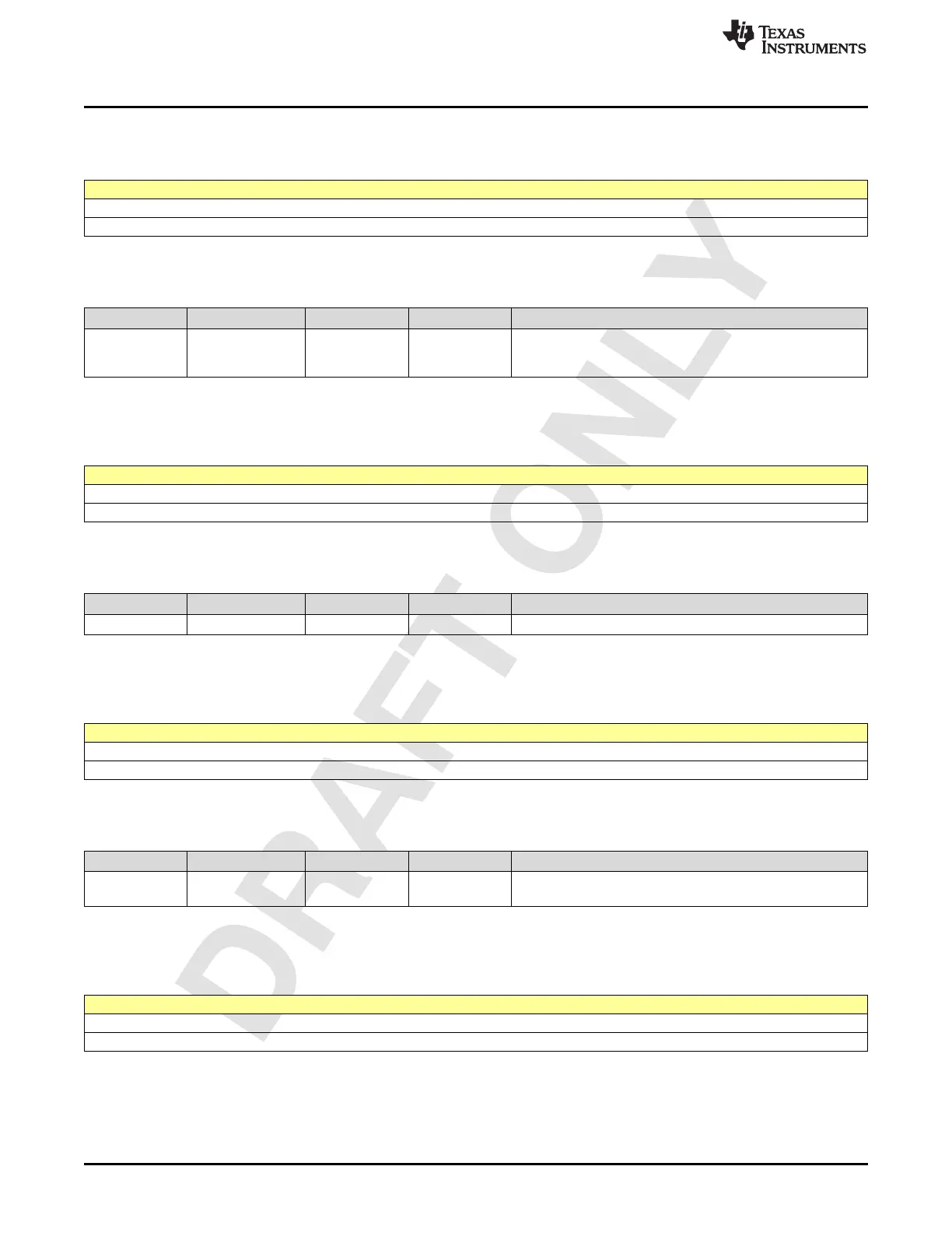
2.16.13 Register 210h (offset = 210h) [reset = 1h]
Figure 2-2276. Register 210h
7 6 5 4 3 2 1 0
PULL_CTRL_GPIO_4
R/W-1h
LEGEND: R/W = Read/Write; W = Write only; -n = value after reset
Table 2-2292. Register 210 Field Descriptions
Bit Field Type Reset Description
2-0
PULL_CTRL_GPIO
_4
R/W 1h
Bit 0 indicates Pull up enable.
Bit <1> Indicates Pull value.
Bit <2> is unused.
2.16.14 Register 211h (offset = 211h) [reset = 2h]
Figure 2-2277. Register 211h
7 6 5 4 3 2 1 0
IBUF_ST_GPIO_4
R/W-2h
LEGEND: R/W = Read/Write; W = Write only; -n = value after reset
Table 2-2293. Register 211 Field Descriptions
Bit Field Type Reset Description
1-0 IBUF_ST_GPIO_4 R/W 2h Input buffer signal strength
2.16.15 Register 212h (offset = 212h) [reset = 0h]
Figure 2-2278. Register 212h
7 6 5 4 3 2 1 0
ODRIV_DS_GPIO_4
R/W-0h
LEGEND: R/W = Read/Write; W = Write only; -n = value after reset
Table 2-2294. Register 212 Field Descriptions
Bit Field Type Reset Description
1-0
ODRIV_DS_GPIO_
4
R/W 0h output buffer drive strength.
2.16.16 Register 214h (offset = 214h) [reset = 1h]
Figure 2-2279. Register 214h
7 6 5 4 3 2 1 0
PULL_CTRL_GPIO_5
R/W-1h
LEGEND: R/W = Read/Write; W = Write only; -n = value after reset